JohnnyGermany
Newbie
Hi!
I am new on this forum, Hi from Germany!
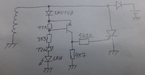
I want to power a 5V arduino circuit from my pitbike single phase stator and I want to build a shunt regulator for it. On the internet I found a schematic for a curcuit like that and my question is:
Would this circuit still be possible just by changing the zener diode to lower the output voltage and adding a capacitor for smoothing? I guess I would also need a load resistor for the magneto since the arduino wont draw much current and the coil would spike up to very high voltages without a load? There is no battery connected to the stator coil since the bike doesn`t have E start just the arduino curcuit.
Unloaded the stator outputs 6 to 80V depending on RPM.
The curcuit is from this Youtube Video:
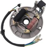
Also added a picture from my stator type.
Thanks very much,
Johannes
I am new on this forum, Hi from Germany!
I want to power a 5V arduino circuit from my pitbike single phase stator and I want to build a shunt regulator for it. On the internet I found a schematic for a curcuit like that and my question is:
Would this circuit still be possible just by changing the zener diode to lower the output voltage and adding a capacitor for smoothing? I guess I would also need a load resistor for the magneto since the arduino wont draw much current and the coil would spike up to very high voltages without a load? There is no battery connected to the stator coil since the bike doesn`t have E start just the arduino curcuit.
Unloaded the stator outputs 6 to 80V depending on RPM.
The curcuit is from this Youtube Video:
Also added a picture from my stator type.
Thanks very much,
Johannes