Continue to Site

Welcome to EDAboard.com

Welcome to our site! EDAboard.com is an international Electronics Discussion Forum focused on EDA software, circuits, schematics, books, theory, papers, asic, pld, 8051, DSP, Network, RF, Analog Design, PCB, Service Manuals... and a whole lot more! To participate you need to register. Registration is free. Click here to register now.

Buffer, selecting op-amp

Status
Not open for further replies.

kalifed

Junior Member level 3
Joined
Jun 21, 2016
Messages
26
Helped
0
Reputation
0
Reaction score
0
Trophy points
1
Activity points
239
Hello everyone,

I am currently reading a lot about the different usages of op-amps, I am getting better but I still have some practical questions.

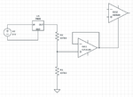
Let's say you want to use an op-amp as a buffer for a simple tension divider:

2016-07-21-10:55:55.png

Suppose that Vin is 3V. How would you proceed to select your op-amp? I would just go fo the highest input impedance...

Thank you!
 

Hi,

I assume the 3.000 V is not your exact continous voltage.
* Instead it has a voltage range. Pleas give us your input signal voltage range.

* What´s the frequency range?
* What attenuation do you want?
* You can´t calculate with "highest input impedance". Give a value. (In your case the input impedance will be domintaed by the resistors)
* What is your supply voltage?
* What is your expected max. output current? (...or output load resistance)
* Is noise an issue?
* What DC precision do you need?
* Do you need DC performance? What precision?
* Do you need AC performance? What precision?

Klaus
 
Thank you for you reply! And sorry for my lack of precision...

The input voltage comes from a 3V linear regulator, which is itself supplied by a battery.
I don't need a high precision on the output voltage, but I need it to be as flat and stable as possible: noise and drift are an issue. The output will be used as a ground reference for an amplifier.

Right now I'm using two 10K 0.1% resistors, with a CA3130 opamp.
 

Hi,

The input voltage comes from a 3V linear regulator
The input_voltage or the supply_voltage for the OPAMP?

but I need it to be as flat and stable as possible: noise and drift are an issue. The output will be used as a ground reference for an amplifier.
Please try to input "as flat as possible" to your calculator..
--> This is no usefull information. Use values.

If really the input is from a linear regualtor, then don´t care about your OPAMP circuit precision. In any case the regulator output will be worse. It varies from device to device, it drifts with time, it drifts with temperature and it drifts with load current.

--> A linear regulator is a power supply device, it is no precision voltage reference device.

Klaus
 
The input voltage is 3V and comes from a linear regulator. The supply voltage of the CA3130 comes from another 5V linear regulator.

As flat as possible => noise < 10uV would be ideal. (The input signal of the amplifier has an amplitude of about 1/20mV, so the noise in the reference has to be << 1/20mV)

Instead of the tension divider would you suggest to use a voltage reference voltage? It would take 3V as an input and ouput the 1.5V needed for my virtual ground reference.
 

Hi,

it´s getting complicated.
Could you provide a schematic or a draft?

***
The input signal of the amplifier has an amplitude of about 1/20mV,
Now you talk about the "other" amplifier, don´t you?

1/20mV = 50uV.

****
voltage divider or reference depends on what your "other" amplifier wants to amplify....
Is it DC, is it AC.....Where does the signal go to?

Klaus
 
Most single power supply opamp circuits DO NOT NEED a precision complicated circuit for a low resistance high current "virtual ground". Instead they use two resistors and a capacitor to make a "half the supply voltage" reference voltage for the opamp's high resistance very low current (+) input voltage reference. Then an input coupling capacitor, an output coupling capacitor and maybe a capacitor to ground on the negative feedback divider.

Why do you need to buffer the output of a voltage regulator that already has a very low output impedance?

Please post the opamp schematic you are playing with.

An old CA3130 opamp is one of the noisiest opamps ever made. Why not use a modern audio opamp instead.
 
I will try to reply to both of you at the same time, here is a schematic of the part of the circuit we are discussing right now:

2016-07-21-14:09:00.png

A 4.5V battery is feeding the 3V linear regulator. Then come the divider with the CA3130 buffer. The output of the CA3130 goes to the ref. of the AD620.

The inputs of the AD620 are: EEG signals. Tension < 50uV, freq between 1Hz and 60Hz. The objective here is to remove the common mode of the two signals and amplify the difference. (And then to filter it but it is not shown here).

Concerning the choices of the components, it is actually the subject of this topic: I know CA3130 is old and noisy, so I want to learn how to select a good replacement. (Same for the AD620 actually, but this is another subject)
 

Attachments

  • 2016-07-21-14:03:53.png
    2016-07-21-14:03:53.png
    18.6 KB · Views: 94

Hi,

Both your pictures are wrong in "battery voltage" and "linear regulator" naming.

*********
Things are getting clearer now.

* I may be wrong, but afaik EEG signals don´t need DC performance, so i see the voltage divider circuit uncritical
* the AD620 REF pin is the output_signal_reference pin. It is less critical against noise and fluctuation than the input pins. (Again, circuit is uncritical)
* The REF signal just lifts the output signal to your desired value. Most probably the AD620 output goes to an ADC with positive only input range.

*******
My recommendation:
if there is an ADC:
* use the ADC_V_Ref to generate the AD620_Ref. simple voltage divider folowed by a low noise buffer circuit.
* supply the low noise buffer with the same supply voltage than the ADC.
* use proper bulk and high frequency debouncing capacitors at each device´s supply pin.
* use proper filtering at the ADC_VRef pin.
* no special care needed for filtering of the AD620_VRef_voltage. (because it cancles out with the ADC_VRef signal)

*****
Device recommendation:
* I assume the signal from the electrodes is more noisy than anything else in your circuit.
* but if you want it to "as be clean as possible", then make the noise on the AD620_VRef pin less than one ADC_LSB.
* check typical electrode impedance (when applied to the human body), then optimize the instrumentation amplifier for this impedance.

total noise = sqrt(voltage_noise^2 + (current_noise x electrode_impedance)^2)
A good start for selection is when the amplifier is called "low noise" and the voltage_noise/current_noise is about equal to electrode_impedance.
I recommend to use excel to calculate and compare some amplifiers.

FET_input amplifier have very low current noise, but some voltage noise. (good for high impedance source)
BJP_input amplifiers have low voltage noise, but some current noise. (good for low impedance source)

Klaus
 
An ECG circuit is similar to an EEG circuit that you want. Its schematic is on the datasheet of your AD620 instrumentation amplifier. It uses an opamp to feed inverted common mode signals to the patient to cancel most of the AC and DC common mode picked up by both inputs.

The reference input on the AD620 is fairly high resistance (20k ohms) and low current (60uA max) so it does not need an opamp buffer.
 
Hi,

It took me a few days to process all the infos in this topic!

*********
Things are getting clearer now.

* I may be wrong, but afaik EEG signals don´t need DC performance, so i see the voltage divider circuit uncritical
* the AD620 REF pin is the output_signal_reference pin. It is less critical against noise and fluctuation than the input pins. (Again, circuit is uncritical)
* The REF signal just lifts the output signal to your desired value. Most probably the AD620 output goes to an ADC with positive only input range.

*******
My recommendation:
if there is an ADC:
* use the ADC_V_Ref to generate the AD620_Ref. simple voltage divider folowed by a low noise buffer circuit.
* supply the low noise buffer with the same supply voltage than the ADC.
* use proper bulk and high frequency debouncing capacitors at each device´s supply pin.
* use proper filtering at the ADC_VRef pin.
* no special care needed for filtering of the AD620_VRef_voltage. (because it cancles out with the ADC_VRef signal)

This is great advice!
My ADC has a range of 0-1.25V, it also has a ADC_VRef pin of 1.25V that I can use as you explained. So that AD620_Ref would be ADC_VRef / 2 = 0.625V
But my AD620 is supplied by 0-5V, is it OK to use an AD620_Ref that is not in the middle (2.5V) of the supply voltage?
(The ref voltage of the AD620 is suppose to "lift" the output, so it should be OK, but I'm not 100% sure!)


total noise = sqrt(voltage_noise^2 + (current_noise x electrode_impedance)^2)
A good start for selection is when the amplifier is called "low noise" and the voltage_noise/current_noise is about equal to electrode_impedance.
I recommend to use excel to calculate and compare some amplifiers.

Using your recommendations I found the OP184FSZ, I think it's pretty good and also comes in "dual" which is nice as I need 2 of them in my circuit.
 

Hi,

Read the datasheet:
V_REF input voltage range is : −VS + 1.6 .... +VS − 1.6
--> Did you mention your supply voltage(s)? 0V / 5V? You should use negative supply. (From the circuit I´m asking why..)

Instead of using the expensive AD620 you could use about any RR I/O OPAMP.

****
noise:
OP184 seems to be a good choice. But not cheap.
 

I was indeed trying to replace the AD620 with a lower power solution (I'd like my circuit to be battery powered).
I found the INA826 which has a RR Output. And V_ref range is -Vs +Vs on that one.

There is also the AD8237 which looks like a great choice (RR I/O as you suggested), low power, V_ref range of -Vs-0.3 ... +Vs+0.3
But since it has a different architecture I can't compare it's noise specs with the INA826. The AD8237 has lower current noise, but how to compare the total voltage noise? Is the Input Voltage Noise Density of the AD8237 equivalent to the RTI of the INA826?
 

A 4.5V battery is probably three alkaline cells. It will quickly drop to about 3.6V then produce only about 3V when the battery needs replacing.
You show a 7805 which is a 5V regulator with a minimum input voltage rating of 7V and a recommended lowest input of 8V. From a battery that drops to only 3V??

Battery powered electronics use low dropout voltage regulators. I looked at what Texas instruments have. I entered a minimum input of 3.6V and a 3V/100mA output and they have 181 different ICs that will do it.

Yes you are definitely right, I am using the 7805 to power the AD620 with 4 alkaline cells (> 6V).
But I am also planning to replace the AD620 (and the CA3130) that both require 5V supply voltage with newer pieces that use lower power (<= 3.3V if possible). Without loss of performance. And for that I am trying to understand how exactly everything works.
I am progressing little by little, that is probably why I can be unclear sometimes (especially a few posts back). Sorry for that!
 

A 6V alkaline battery will quickly drop to 4.8V.
The minimum input for a 7805 is 7V so it will not work.
A 5V low dropout regulator has a minimum input of about 5.5V.
 

Attachments

  • 7805 voltage regulator.png
    7805 voltage regulator.png
    8.5 KB · Views: 88

Indeed I am using the LP2980AIM5-5.0, I used an online software to do the schematic I posted here so I guess it was the default...
 

You still cannot use a 6V alkaline battery to power the ultra low-dropout 5V regulator because the battery will quickly drop lower than the minimum input voltage.
Energizer make AA Lithium batteries that hold up their voltage pretty well.
 
Yes, that is exactly why I'm trying to reduce the supply voltage of the circuit. A 3.5-4V battery is way cheaper and easier to find than 6V

I was indeed trying to replace the AD620 with a lower power solution (I'd like my circuit to be battery powered).
I found the INA826 which has a RR Output. And V_ref range is -Vs +Vs on that one.

There is also the AD8237 which looks like a great choice (RR I/O as you suggested), low power, V_ref range of -Vs-0.3 ... +Vs+0.3
But since it has a different architecture I can't compare it's noise specs with the INA826. The AD8237 has lower current noise, but how to compare the total voltage noise? Is the Input Voltage Noise Density of the AD8237 equivalent to the RTI of the INA826?

Any comment on this?
 

Status
Not open for further replies.

Similar threads

Part and Inventory Search

Welcome to EDABoard.com

Sponsor

Back
Top