Continue to Site

Welcome to EDAboard.com

Welcome to our site! EDAboard.com is an international Electronics Discussion Forum focused on EDA software, circuits, schematics, books, theory, papers, asic, pld, 8051, DSP, Network, RF, Analog Design, PCB, Service Manuals... and a whole lot more! To participate you need to register. Registration is free. Click here to register now.

Buck Converter CCM with high ripple current

Status
Not open for further replies.

joyu

Newbie level 5
Newbie level 5
Joined
Feb 11, 2007
Messages
10
Helped
0
Reputation
0
Reaction score
0
Trophy points
1,281
Activity points
1,365
I am looking for a good resource on the negative effects of having high ripple current with a buck converter at low load.

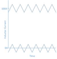
Most resources agree that you should design your ripple current around 20% of your maximum current. If you have a design with a huge swing between maximum and minimum output load current, this 20% rule can end up with significant negative inductor current when operating at the minimum output in CCM mode.

What are the adverse affects of operating in this minimum power mode with CCM?
Ripple.png

Reasons for the 20% guideline I have read so far
-Less Current Ripple -> Less Caps (Less $)
-Less Current Ripple -> Less EMI

What I am really looking for is what kind of component failures we might see operating with this large negative current through the inductor (which will flow through to the input caps for part of the time).
 

A normal switched-coil converter does not have reverse current flow in the inductor.

In a buck converter, the inductor acts as a choke. In a manner of speaking, it averages pulsed DC.
 

Well, there will be reverse current during (some portion of)
the low phase if average current is less than ripple current.
But the inductor doesn't care.
 

The negative current only happens when you have synchronous rectification, otherwise it will transition to DCM. The negative current at light load is bad from an efficiency standpoint, but can be desirable from a control standpoint, since it means the response of the converter doesn't change abruptly when transitioning between CCM and DCM.
 

The negative current only happens when you have synchronous rectification, otherwise it will transition to DCM. The negative current at light load is bad from an efficiency standpoint, but can be desirable from a control standpoint, since it means the response of the converter doesn't change abruptly when transitioning between CCM and DCM.

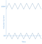
Yes we are talking about CCM (Continuous Conduction Mode) operation, the attachment in the first post shows what I am talking about, the inductor current is negative for almost half the cycle in the no load case. I am trying to see if there are considerations that need to be made when you know you are going to be operating at low load for long periods of time. I want a good reference that talks about this, again specifically regarding what components might fail.

Reposting picture from original post.
 

There's no reason to believe that the negative currents would cause component failure in a synchronous converter, because a synchronous converter is designed with components that pass current in both directions (basically you replace diodes with FETs). The stress on these components is dependent on the RMS current, the sign is irrelevant.
 

I agree in theory, in practice I am wondering if there are other extra design considerations that need to be made. The stress on the components is not only based on RMS current, the ripple current has a lot of design considerations for example the output cap sizes etc.

When designing the circuit we design the amount of ripple current based on the max load situation. Now the circuit is spending a lot of time in this low load situation which causes interesting behavior. The output caps are now sourcing the current both towards the load and back towards the source. The input caps are now sinking current from the output side when in negative current and high side FETs active.

Because we are spending a lot of time in this mode do we have to make extra design considerations because of downstream buck converters who now may be pulling a lot of current from the output caps at the same time which could be significant with overlapping frequencies etc?
Other considerations?

I just can't find much information about design considerations when in low load. Maybe there is a good book about Synchronous Buck converter design that would talk more about extreme cases?
 

I agree in theory, in practice I am wondering if there are other extra design considerations that need to be made. The stress on the components is not only based on RMS current, the ripple current has a lot of design considerations for example the output cap sizes etc.

When designing the circuit we design the amount of ripple current based on the max load situation. Now the circuit is spending a lot of time in this low load situation which causes interesting behavior. The output caps are now sourcing the current both towards the load and back towards the source. The input caps are now sinking current from the output side when in negative current and high side FETs active.
The ripple current in a capacitor is the same as the rms current (rms is more important than peak to peak for caps). Capacitors always conduct AC, and only AC. The capacitor literally cannot distinguish the two waveforms you've drawn, because it is a capacitor.

The passive components will not be bothered at all by the negative current. The FETs should not care so long as they are driven properly. The only catch I can think of is the current sense circuitry, which needs to tolerate negative currents. But even then you are probably only going to be interested in the peak current, which should always be positive (at steady state).
 
  • Like
Reactions: joyu

    joyu

    Points: 2
    Helpful Answer Positive Rating
The ripple current in a capacitor is the same as the rms current (rms is more important than peak to peak for caps). Capacitors always conduct AC, and only AC. The capacitor literally cannot distinguish the two waveforms you've drawn, because it is a capacitor.

I agree with your conclusion, what I was saying is that the ripple current does have to be taken into account when choosing the cap, I was thinking of RMS current differently than what you are describing.

I agree about the current limits. The negative current limit needs to be set according to the negative peak current along with setting the positive current limit according to the positive peak current.

Let me know if you think of anything else to watch out for. Thanks!
 

Status
Not open for further replies.

Similar threads

Part and Inventory Search

Welcome to EDABoard.com

Sponsor

Back
Top