azarutz
Member level 2
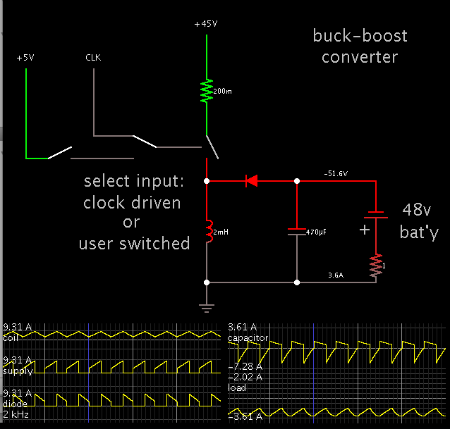
Hi i designed a buck boost converter (inverted topology) to charge 4, 12v lead acid battery each capacity is 100 Ah .
buck boost circuit spec is 20 to 70 V input and 54 V output .

i have to limit the starting current of the inductor actually i designed it for max 15A but it goes to 42A at starting .it showed in pic with circled in rose color.

1) is there any way to limit the starting current to inductor without affecting normal operation ?
2) voltage across capacitor is taken to battery. is it work in that way?
thanks in advance .
buck boost circuit spec is 20 to 70 V input and 54 V output .
i have to limit the starting current of the inductor actually i designed it for max 15A but it goes to 42A at starting .it showed in pic with circled in rose color.
1) is there any way to limit the starting current to inductor without affecting normal operation ?
2) voltage across capacitor is taken to battery. is it work in that way?
thanks in advance .