Continue to Site

Welcome to EDAboard.com

Welcome to our site! EDAboard.com is an international Electronics Discussion Forum focused on EDA software, circuits, schematics, books, theory, papers, asic, pld, 8051, DSP, Network, RF, Analog Design, PCB, Service Manuals... and a whole lot more! To participate you need to register. Registration is free. Click here to register now.

[SOLVED] Boostrap capacitor charging confusion

Status
Not open for further replies.

abc_de

Full Member level 5
Joined
Jan 9, 2014
Messages
243
Helped
11
Reputation
22
Reaction score
11
Trophy points
1,298
Location
Ludhiana ਪੰਜਾਬ
Activity points
2,939
Hello
For 3 phase sine wave inverter for acim motor
What happen if I don't do boostrap capacitor charging. I direct start pwm sequence for sine wave generation.
Does it below switching device ?
What is exact way to charge boostrap capacitor by permanent ON low side switching device for fraction of second or by multiple pulses applied to low side switching device
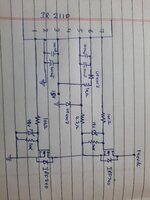
 

Ok
driver is ir2110 @15v mosfet irf740
 

Attachments

  • 20220202_125141.jpg
    20220202_125141.jpg
    1.6 MB · Views: 119

Hi,

Oh, you talk about the bootstrap capacitor of a mosfet driver IC.
(You did not mention: MOSFET, MOSFET driver, IR2110. And "bootstrop capacitor" is a rather general phrase for a capacitor that lifts up some voltage. Bootstrap capacitors are used in many circuits, like analog audio amplifiers...)

The manufacturer of the IR2110 provides datasheet and additional information on "switching MOSFETs circuits. Please go to the manufacturer's internet site for this IC and look for "application notes" and "design notes". This is where I have my knowledge from.

In short:
The bootstrap capacitors are charged when the LOW side MOSFET is ON.
But in your case there is a 4.7 Ohms and a 10 Ohms resistor in series. These are counter productive for fast charging of the capacitor.
I can't remember the datasheet of the IR2110 recommends to use these resistors. I'd omit these resistors.
Where is your schematic from?

The resistors in combination with the capacitor create a charging delay according: tau = R × C

Signal flow: 15V --> 10 R --> diode --> capacitor --> 4R7 --> MOSFET --> GND

Klaus
 
Last edited:

With relative low bootstrap capacitance of 10 uF, you probably don't need a series resistor, at least not so large. I see however a specific problem with 4.7 ohm resistor, it generates a positive gate voltage during bootstrap capacitor charging.

Regarding precharge sequence, it's surely application dependent. If you start with zero load voltage, you can simply activate all LS switches for a certain time. With existing load voltage, e.g. an inverter starting against rotating motor, only one swicth can be activated at a time.
 
Hi,

You give no information about
* switching frequency
* duty cycle range.

No feedback about the resistors we talked ... and the application notes.
****

So I just answer to your 3x ON during startup:
* It is risky to switch all three LOW side MOSFETs ON without PWM. This is when after a short power loss or when any other RESET happens the rotating motor may cause short circuit currents.
--> In worst case the LOW side MOSFETs may explode.

Klaus
 

Switching frequency: 2khz
Duty cycle: 5% to 95%
4.7ohm resistor and 10ohm resistor play role in charging of boostrap capacitor also below up in worst case and protect ir2110( after field testing).
I am thinking when load is off then all or one low side mosfet on.
--- Updated ---

Switching frequency: 2khz
Duty cycle: 5% to 95%
4.7ohm resistor and 10ohm resistor play role in charging of boostrap capacitor also below up in worst case and protect ir2110( after field testing).
I am thinking when load is off then all or one low side mosfet on.
If this is unsafe then what will be another way?
 

Hi,

Wiht 95% duty cycle @2kHz and omitting the resistirs you should not expect any bootstrap voltage problems at all.
Even with the resistors .... it may just take a couple of PWM cycles for the HIGH side to operate correctly. Not a problem at all.

An asynchronous motor can act as generator ... it can/will generate current.

--> I'd avoid short circuiting the motor ... by switching ON LOW side (one or multiple MOSFETs) without useful PWM.

Klaus
 
  • Like
Reactions: abc_de

    abc_de

    Points: 2
    Helpful Answer Positive Rating
Hi,
it may just take a couple of PWM cycles for the HIGH side to operate correctly
Just to clarify:
The bootstrap circuit will operate correctly. But I still recommend to omit the resistors, unless there is a good reason for using them.

In doubt: Refer to the driver IC manufacturer´s documents.

Klaus
 
  • Like
Reactions: abc_de

    abc_de

    Points: 2
    Helpful Answer Positive Rating
Status
Not open for further replies.

Similar threads

Part and Inventory Search

Welcome to EDABoard.com

Sponsor

Back
Top