goli619
Newbie level 4
Hello everyone, please help...
When i connect the circuit as the schematic above: the output is not changeable which means when I alter my Pot, the output remains the same. ( the frequency is about 2.3Khz)
One thing that I have observed is, the output is now depending on my Inductor value.
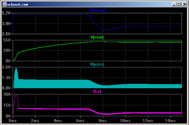
1mH = 100V++;10mH= 51V.
I burned my 3mH inductor while I was using C1=47uF (last time, the inductor wasn't burned !!! I wonder why)
The duty cycle is about 60%.
Things that I've summarized are :
1. When switching frequency is up to 23kHz, the inductor is alright but the output is not alterable; When switching frequency is low as 1.4kHz, the output can be altered but inductor will be burst ( it's like overheat and cause the outside(cover) of the coil inductor melts.)
2. The feedback system seems like failure when frequency is as high as 20kHz. But, why?
3. For 1 &2 are the conditions under resistor as load. And, I just connected it to the real load that I wanted to connect. Things happen:
The output voltage was less than just now: for 10mH, it became 30V;for 1mH, it became 80V [the output voltage is less 20V compare the just now]
(ii) When I connected to 1mH inductor, both of the inductor and Mosfet is quite hot ( i just connect it about 10++min)
4. Previously, with low frequency, it had "hiss" sound. Now, "Hiss" sound is gone when the switching frequency is 20kHz with 60%duty cycle; "hiss" sound appears when switching frequency is 1.4kHZ...
Does anyone have any ideas regarding my problem? What should I do? Thanks a lot in advanced.
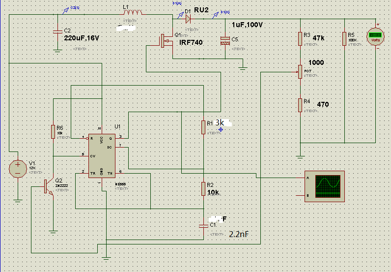
When i connect the circuit as the schematic above: the output is not changeable which means when I alter my Pot, the output remains the same. ( the frequency is about 2.3Khz)
One thing that I have observed is, the output is now depending on my Inductor value.
1mH = 100V++;10mH= 51V.
I burned my 3mH inductor while I was using C1=47uF (last time, the inductor wasn't burned !!! I wonder why)
The duty cycle is about 60%.
Things that I've summarized are :
1. When switching frequency is up to 23kHz, the inductor is alright but the output is not alterable; When switching frequency is low as 1.4kHz, the output can be altered but inductor will be burst ( it's like overheat and cause the outside(cover) of the coil inductor melts.)
2. The feedback system seems like failure when frequency is as high as 20kHz. But, why?
3. For 1 &2 are the conditions under resistor as load. And, I just connected it to the real load that I wanted to connect. Things happen:
The output voltage was less than just now: for 10mH, it became 30V;for 1mH, it became 80V [the output voltage is less 20V compare the just now]
(ii) When I connected to 1mH inductor, both of the inductor and Mosfet is quite hot ( i just connect it about 10++min)
4. Previously, with low frequency, it had "hiss" sound. Now, "Hiss" sound is gone when the switching frequency is 20kHz with 60%duty cycle; "hiss" sound appears when switching frequency is 1.4kHZ...
Does anyone have any ideas regarding my problem? What should I do? Thanks a lot in advanced.