Continue to Site

Welcome to EDAboard.com

Welcome to our site! EDAboard.com is an international Electronics Discussion Forum focused on EDA software, circuits, schematics, books, theory, papers, asic, pld, 8051, DSP, Network, RF, Analog Design, PCB, Service Manuals... and a whole lot more! To participate you need to register. Registration is free. Click here to register now.

Bob beck magnetic pulser

Status
Not open for further replies.

Haf2eez

Newbie level 6
Joined
Sep 12, 2020
Messages
11
Helped
0
Reputation
0
Reaction score
0
Trophy points
1
Activity points
69
Hi

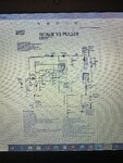
I need a help on this attached circuit diagram, which I’m planning to make it as a hobby Magnetic pulser circuit. In this I have a doubt on Pchannel mosfet IRFD9024. How it is connected to the comparator LM311? which lead is the Drain, source and gate for this IRFD 9024. I tried referring to the data sheet but I couldn’t make it. If you can help me that would be much helpful.
 

Attachments

  • 587ACFA0-DD79-4DF0-A336-3A89597AF2F9.jpeg
    587ACFA0-DD79-4DF0-A336-3A89597AF2F9.jpeg
    5.2 MB · Views: 533

Hi,

Left to right: gate, drain, source.

Logically/by reasoning a bit: the gate is controlled by the comparator, the drain is the output pin, and the source is where power comes into the PMOS from the supply.
 

Hi,

did you really take a 5Megabytes photo of low quality from a PC monitor?
Why no link to the source, why no PNG screenshot or upload (a part of) the document?
Then we could at least read what´s written on the schematic.

to me it it seems that there is an additional letter before the "IRFD"...

Klaus
My Apologies for uploading the low pixel pic.
 

For safety, solder a whole bunch, say 5, 10A10 diodes across your high voltage storage caps - thus if the SCR goes short the pulse will still be unipolar and you won't blow the caps up - also always choose an SCR with 8.33/10mS Ipk rating about twice your expected peak current, also do not exceed the di/dt rating of the SCR ( read data-sheet carefully ),
We have a similar (power) ckt at work that makes 2.5kA for magnetising hard ferrites, from 400V, 4000uF - with carefully controlled coil structures.

You may find the MCR25 at 300A rated pk is a little small for this work, we have a 6kA rated SCR ( hockey puck style )
--- Updated ---

Also in the ckt shown the PNP will likely be on all the time ....
 

Than
For safety, solder a whole bunch, say 5, 10A10 diodes across your high voltage storage caps - thus if the SCR goes short the pulse will still be unipolar and you won't blow the caps up - also always choose an SCR with 8.33/10mS Ipk rating about twice your expected peak current, also do not exceed the di/dt rating of the SCR ( read data-sheet carefully ),
We have a similar (power) ckt at work that makes 2.5kA for magnetising hard ferrites, from 400V, 4000uF - with carefully controlled coil structures.

You may find the MCR25 at 300A rated pk is a little small for this work, we have a 6kA rated SCR ( hockey puck style )
--- Updated ---

Also in the ckt shown the PNP will likely be on all the time ....
Much Appreciated for the help. Just wanted to know if the PNP is on all the time it won’t Produce the Pulse ?
 

This is the YouTube link for the above circuit.


Status
Not open for further replies.

Part and Inventory Search

Welcome to EDABoard.com

Sponsor

Back
Top