Continue to Site

Welcome to EDAboard.com

Welcome to our site! EDAboard.com is an international Electronics Discussion Forum focused on EDA software, circuits, schematics, books, theory, papers, asic, pld, 8051, DSP, Network, RF, Analog Design, PCB, Service Manuals... and a whole lot more! To participate you need to register. Registration is free. Click here to register now.

bleed resistor formula needed

Status
Not open for further replies.

satiz

Member level 5
Joined
Jun 9, 2013
Messages
87
Helped
3
Reputation
6
Reaction score
3
Trophy points
1,288
Activity points
1,999
Hi All,

Need formula to calculate bleed resistor :

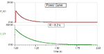
My circuit is attached below. Please guide me to select correct bleed resistor. I need to discharge the cap with in 1 sec (approx) after removing the power source.

Bleed.png
 

Vc= V * e-t/R*C

Where Vc is the voltage you want the capacitor discharged to.
If you set it to zero, it would take an infinite time o do so.
 
Last edited:

Hi,

Tau = R x C.
This means discharged to about 37% of inital value.

I need to discharge the cap with in 1 sec (approx) after removing the power source.
Fully deleted to 0.000mV? Or what level?

So we don't have the initial voltage level and we don't have the discharged_voltage_level.
You need to define both, then you can calculate it on your own:

Count of tau = ln (inital_volt / disch_volt)

Klaus
 

Hi Thanks for your reply, capacitor initial volt is 312 and expected discharge volt is approx 1 or 2 Volts
 

Ok,
you now have got the formulas.

Calculate how many taus you require o discharge your voltage within one second,
then as you already have the "C" value, you can find the "R"
 

Ok,
you now have got the formulas.

Calculate how many taus you require o discharge your voltage within one second,
then as you already have the "C" value, you can find the "R"

Count of tau = ln (inital_volt / disch_volt)
=312/2
=5.04
5= R*(22uF)
R = 5/22uF
R=0.2727 ohms ?
 

You sure you want 1-2V? That's another couple time constants from say 12, or 40 which is a common number from a safety perspective.

Also 1 second is pretty fast.

Cap discharge is actually a bit tricky because when you do the math you'll see that if you rate a device for the worst case wattage it will be a large device. So you'll probably want to find devices that are rated for the amount of joule's in your cap but then it's a bit harder to find devices that properly spec joule ratings, surge ratings etc - though they're out there. You will want to specifically google "cap discharge resistor" or "resistor joule rating" in order to find them.

But if you rate a device only for joule's you need to guarantee that you can switch that device out of the circuit and guarantee that on power loss it switches back in.

Another option I've explored and may implement is a constant current discharge circuit using this:
IXCP10M45S

Constant current is advantageous because the discharge is linear and doesn't slow down as voltage decreases (particularly useful if you really want to get to 1-2V). Constant current is also convenient because you can use it to power a red LED consistently until the voltage is entirely gone.

I was also looking at PTC's specifically rated for cap (dis)charging which you can find by searching "cap charge ptc". The beauty of the PTC is that it can have a low ohm value initially for a fast discharge but if it overheats it self limits. Though all PTCs have this property this one is specially rated for this application.
https://datasheet.octopart.com/B59201J0140B010-EPCOS-datasheet-5398620.pdf
 
This is overkill but this is a circuit I had previously mocked up which adds a TL431 in a constant-current topology but with a resistor biasing the feedback from the cap voltage. The result is that current is decreased at higher voltages which significantly reduces maximum power dissipation for a given discharge rate.

There are a lot of ways to configure this. As shown it can be left in all the time and is set up so wattage reduces somewhat at the peak operating voltage of 400V to ~0.5W to limit steady state power loss and heat. During discharge it never exceeds 1W.

A resistor with a similar discharge time to ~10V would burn an order of magnitude or so more power at steady state (which is either wasteful and large or necessitates an off switch of some kind)

KZnY2Sr.png
 

Once you figured the required resistor, you should also pay attention to the power rating required.
 

Attachments

  • disch.png
    disch.png
    8.4 KB · Views: 74

Hi,

P= U x U / R....
So with 312V and 270k it's just below 0.5W.

Klaus
 

270k doesn't come close to the requested discharge time though? Even assuming a reasonable increase in either time or voltage we're talking about 25k or less which is ~4W or more at 312V
 

I don't believe that the idea to achieve sufficient fast discharge without high quiescent power dissipation by applying a non-linear load are practical. One problem is to guarantee operation over a varying input voltage range, including irregular undervoltage situations.

Known technical solutions are using a load switch controlled by an input voltage detector. The load resistor should be of the PTC type for self protection in unexpected situations.

My math gives 9k load resistor (200 ms time constant) to discharge 312 to 2 V in 1 sec (5 time constants).

I wonder if the requirements are well substantiated or just the result of misunderstood regulations.
 

Hi,

Count of tau = ln (inital_volt / disch_volt)
=312/2
=5.04
5= R*(22uF)
R = 5/22uF
R=0.2727 ohms ?

Now I recognize the mistake.
"5.04" is the count of tau, it means you need 5.04 tau to discharge the capacitor.

Now if 5 tau = 1s, then 1 tau = 0.2s
Now tau = R x C,
So R = tau / C = 0.2s / 22uF = about 9kOhm

Klaus
 

I don't believe that the idea to achieve sufficient fast discharge without high quiescent power dissipation by applying a non-linear load are practical. One problem is to guarantee operation over a varying input voltage range, including irregular undervoltage situations.

Known technical solutions are using a load switch controlled by an input voltage detector. The load resistor should be of the PTC type for self protection in unexpected situations.

My math gives 9k load resistor (200 ms time constant) to discharge 312 to 2 V in 1 sec (5 time constants).

I wonder if the requirements are well substantiated or just the result of misunderstood regulations.

I'm not thinking it's worth it either though the wattage reduction at operating voltage I'd call a 'nice to have'. If implemented it should be designed to sustain peak power for the reason you mention. I think of the circuit as simple but somewhat effective approximation of 'constant power' which has obvious benefits for load discharge.

On the other hand a circuit that switches on only when power is removed, besides potentially being simpler (though not a ton when switch circuitry is considered), can make use of the heat capacity of its load element and/or the board etc and in this case there are a very small number of Joules.

Looking at PTC's I come up with this device. Note that with a heat capacity of 5J/C this won't even rise a degree to discharge the specified 22uF cap. That suggests a much smaller PTC could be used. However on a quick look I fail to find smaller devices that specify heat capacity in their datasheets.
https://www.ametherm.com/inrush-current/inrush-ptc-thermistor

This family is also promising:
https://en.tdk.eu/inf/55/db/PTC/PTC_ICL_OC_Leaded_260V_1000V.pdf
 
Last edited:

I'm still thinking about this because its overlapping with a similar application of my own where I've got a removable module that gets a 400V bus and naturally has some C, perhaps 100u. The module has a male gold finger edge connector so, although "hot swapping" isn't supported it's possible and it would leave 400V exposed on the gold fingers. This means I either want a switch to block the 400V in the backwards direction or a discharge that's actually on the order of 1S (though not to 2V, it just needs to get down to ~20V or so to be safe).


Anyway, what I wanted to add is that I researched the heat capacity of some common components and what I find is that almost any standard power package can dissipate the handful of Joules in the OP's application and my application (100uF@400V=8 Joules).

This TI app for a soft start circuit puts a D2pak at 1C/J. What that means is that a load element isn't technically necessary, you can fire a mosfet and let it burn down the bank as fast as you want. Safe operating area may still apply, but with a low number of Jouls I suspect the discharge should fit easily under those curves.
https://www.ti.com/lit/an/slva158/slva158.pdf

The problem remains how to make sure the circuit is safe even if it misfired. I see a few options:
1) Rely on a fuse to blow
2) Add back the PTC primarily for its fault protection ability
3) Limit the fet discharge to a reasonable number of watts that would slow overheating to, say 5-10 seconds and work in a thermal shutdown like a small non-linear PTC in the enable circuit for example.

One is probably reasonable in many cases and although 3 is interesting by trying to optimize around a single power element 2 is probably the simplest/best option.
 

From a minimal circuit complexity viewpoint, I would opt for MOSFET switch + PTC.
 

From a minimal circuit complexity viewpoint, I would opt for MOSFET switch + PTC.

You have sparked my interest... I am guessing you are talking about using the PTC in a voltage divider to bias the gate of the mosfet. Is this correct?

Thanks
 

Status
Not open for further replies.

Part and Inventory Search

Welcome to EDABoard.com

Sponsor

Back
Top