Continue to Site

Welcome to EDAboard.com

Welcome to our site! EDAboard.com is an international Electronics Discussion Forum focused on EDA software, circuits, schematics, books, theory, papers, asic, pld, 8051, DSP, Network, RF, Analog Design, PCB, Service Manuals... and a whole lot more! To participate you need to register. Registration is free. Click here to register now.

BLDC inline phase current measurement

Status
Not open for further replies.

jakub0

Newbie level 4
Joined
Oct 19, 2022
Messages
6
Helped
0
Reputation
0
Reaction score
0
Trophy points
1
Activity points
36
Hi everyone,

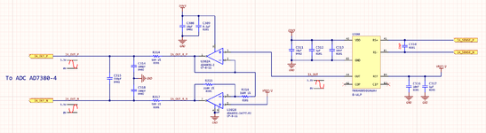
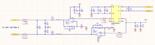
I am designing circuit to measure the inline currents of each BLDC motor phase. Because the ADC (AD7380-4) has fully differential analog inputs I came up with 2 different solutions of how to connect the CSA (MAX40056U) to the ADC:

- use the pseudo-differential signal or

- convert single-ended signal to fully differential one

Below I attached two schematics. I would like to ask you to have a look and say if they are correct and which way is more proper. Thank you in advance.
 

Attachments

  • s0.png
    s0.png
    81.9 KB · Views: 114
  • s1.png
    s1.png
    76.6 KB · Views: 112

Hi,

what is the measurement used for?
Just coarse current measurement, regulation loop, short circuit detection, detection of DC voltage, phase shift detection, ....
Is the measurement timing critical (delay, phase shift...)? (limits..)
What is your decided ADC sampling frequency?

I wonder what´s the idea of using a current sense amplifier with 300kHz followed by a 230,000kHz amplifier.
I mean it´s almost 1000 times the frequency.

On first sight, I´d go with the first circuit.
But it really depends on what signal information you are after.

Klaus
 

It is the inline motor phase current measurement for the FOC algorithm (3 phases) which will run with frequency in range 40kHz to100kHz. I see your point about the bandwidth. The OPAMP is recommended by Analog Devices as a driver for this ADC. That is the only reason why I want to use this particular one.
And thank you for your quick reply.
 

Hi,

is it 40kHz .. 100kHz PWM frequency or fundamental (motor magnetic field) frequency?

I guess in case of FOC you are interested mainly in fundamental frequency and it´s phase information.
So FOC is not interested in "PWM frequency as input". (Correct me if I´m wrong. Thus I asked whether your measurement is timing critical)

If so, then I recommend to put an LPF in front of the current sense amplifier to ease the analog signal processing
(easier, because of lower dV/dt)

OPAMP for ADC:
If you want to use it at 4MSmpls/s it makes sense. Thus I asked for the sampling frequency.

The first circuit you mean to use the pseudo-differential signal?

s0.png.
I´d call it "true differential".

Klaus
 

I am not sure what you mean saying fundamental frequency. If I understand correctly the fundamental frequency is the frequency of the main FOC loop. In this way I agree the fundamental frequency and the PWM frequency are two different things. But as I understand they can be the same (like is in my case).
 

Correct s0.png is fully differential and the s1.png is pseudo-differential because AIN- is the VREF
 

I implemented it in ltspice, screenshot and project below. I still cannot make it work with voltage source LTC6655 but for now it is not a blocker. Maybe could you have a look at it? Thanks in advance
 

Attachments

  • adc.png
    adc.png
    62.3 KB · Views: 114
  • adc_front_end_ada4896-2.zip
    1.5 KB · Views: 101

Status
Not open for further replies.

Similar threads

Part and Inventory Search

Welcome to EDABoard.com

Sponsor

Back
Top