Vermes
Advanced Member level 4
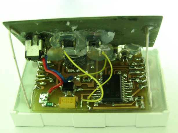
This version of binary clock is based on LED matrix LINK, processor Attiny2313 and RTC DS1307. Everything except the matrix is in SMD technology.
Schematic:
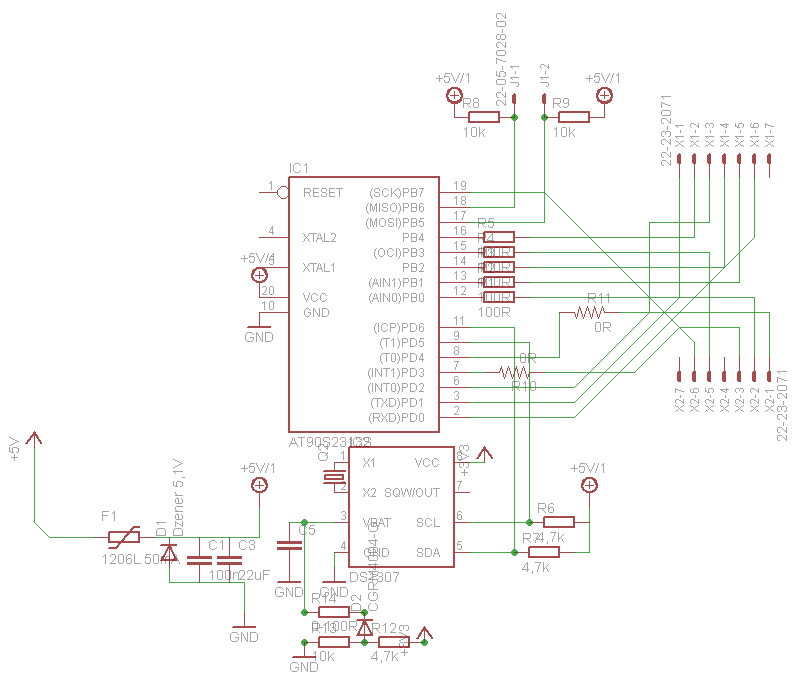
Order of pins on the schematic corresponds to the pins of matrix. Code takes 1,87kB.
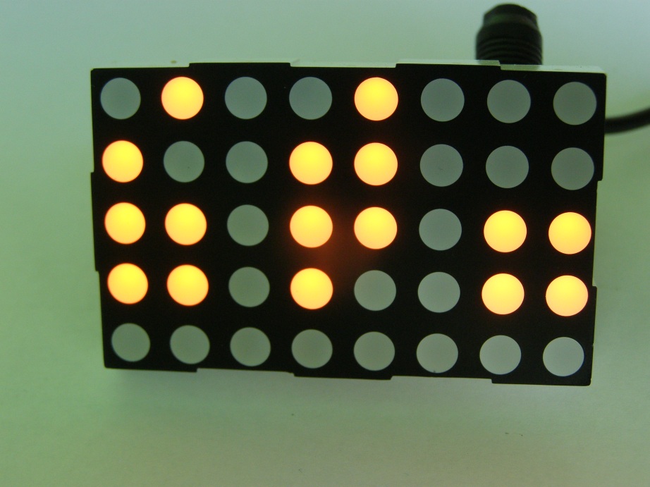
The clock displays time in the form of BCD code, what provides fast read. The clock allows you to display in few modes:
- standard BCD
- BCD with byte field backlight of intensity 1
- BCD with byte field backlight of intensity 2
- BCD with byte field backlight of intensity 3
- BCD with byte field backlight of intensity 4
- BCD with byte field backlight of intensity 5 – very bright
- BCD in the reverse logic lit=0, not lit=1
The whole device is multiplexed with a frequency of about 1kHz.
How to read the device:
- 1 row – tens of hours
- 2 row - unities of hours
- 3 row – tens of minutes
- 4 row – unities of minutes
- 5 row – tens of seconds
- 6 row – unities of seconds
And in a row from the top – diode number:
- 1 = 1
- 2 = 2
- 3 = 4
- 4 = 8
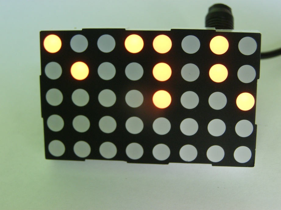
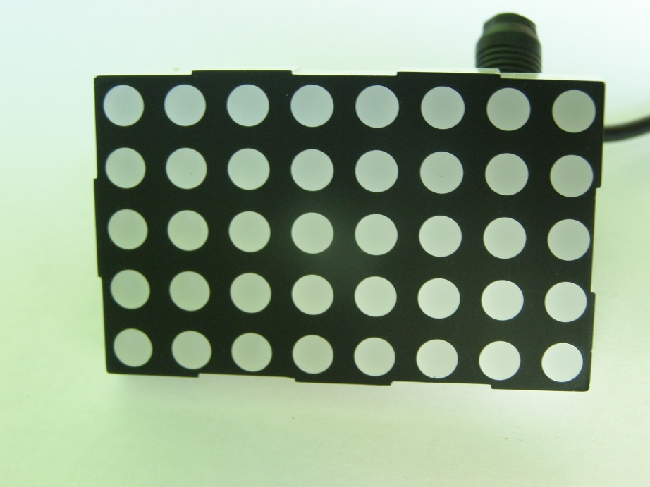
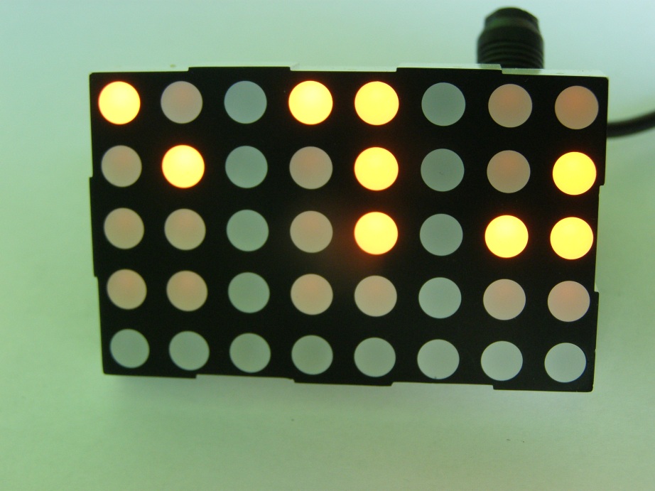
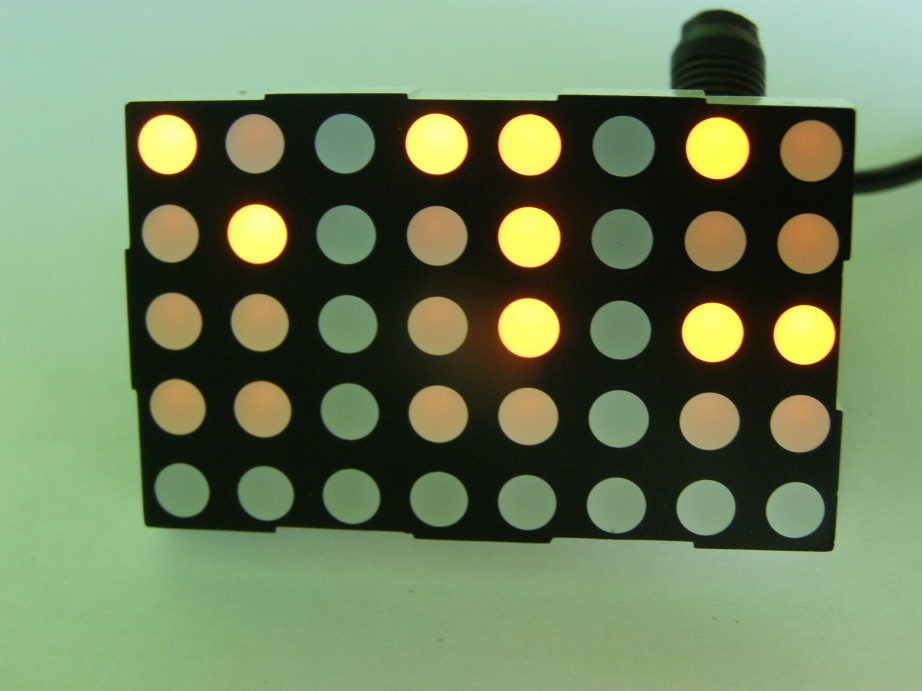
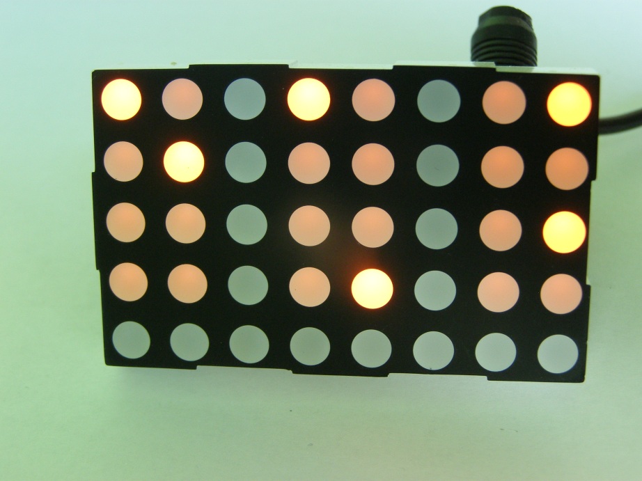
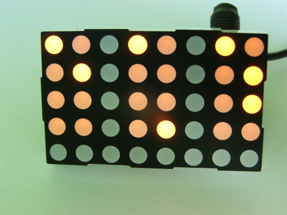
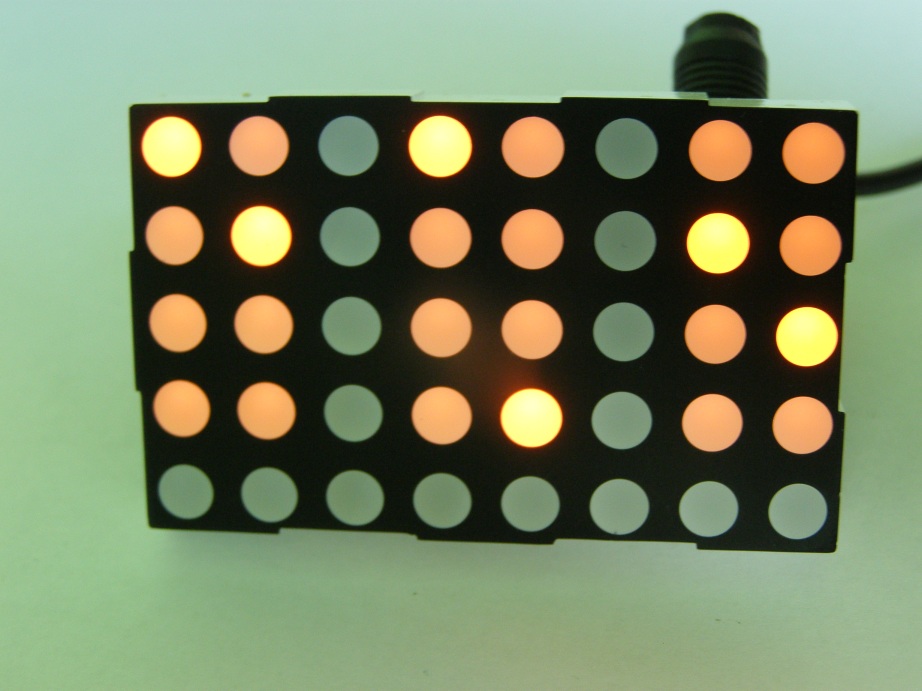
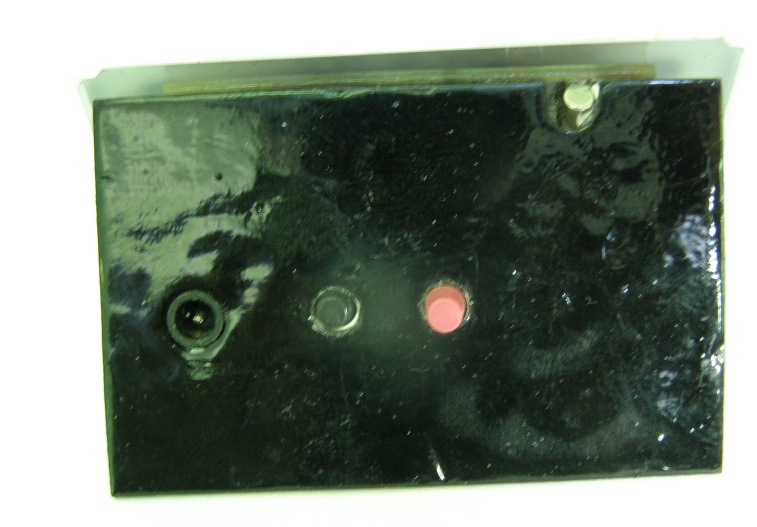
Pictures:

Video:
Link to original thread (useful attachment) – Zegarek binarny na matrycy LED