Continue to Site

Welcome to EDAboard.com

Welcome to our site! EDAboard.com is an international Electronics Discussion Forum focused on EDA software, circuits, schematics, books, theory, papers, asic, pld, 8051, DSP, Network, RF, Analog Design, PCB, Service Manuals... and a whole lot more! To participate you need to register. Registration is free. Click here to register now.

Beginners confusion... (water detect transistor circuit)

Status
Not open for further replies.

Alistair Ballantyne

Junior Member level 2
Joined
Jan 9, 2021
Messages
20
Helped
0
Reputation
0
Reaction score
0
Trophy points
1
Activity points
229
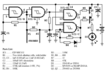
I made this simple water tester circuit from the Electronics for Dummies book.
Three issues –
The circuit works but only without the resistor (R2) between base and emitter. Put this in and the circuit fails. Why? I don’t understand. Is there something wrong with my wiring?
Given the current will flow through the path of least resistance doesn’t that mean I have 8.3v (9vcc – 0.7v VBE) going into the base – and wont that damage the transistor?
Is the resulting hFE not so large as to damage the LED?
Or should I be looking at the entire circuit and calculating current at base as 0.013A?
(9v VCC - 2v LED - 0.7v BE) / 470Ω = 0.013A.
Appreciate any help.
Thank you.
1611749601352.png

1611749616887.png
 

That is a BAD design. Shorting the probes together will damage the transistor and possibly R2 as well.

The current through the LED is limited by two factors, the value of R1 and how much the transistor is conducting. Good design practice says take the worst case scenario of the transistor fully conducting (as though it has a short between collector and emitter) and set R1 to a value that protects the LED. I'm assuming from your calculation that the battery is 9V and R1 is 470 Ohms so if we assume the LED drops about 1.75V and the transistor is fully conducting, the LED current will be (Vbattery - Vled)/470 or about 15mA which is a perfectly acceptable amount.

How much the transistor conducts between collector and emitter will depend on the current allowed to flow into the base pin. The idea behind the circuit is the resistance between the probes ( = the amount of conduction through the water) provides the base current from the positive side of the battery. Some of the probe current will also go through R2 instead of the base so varying it's value will change how much is diverted away from the base and hence how 'sensitive' to conduction the probes appear to be. Note that if R2 is set to minimum resistance and the probes touch each other it shorts out the battery!

I would do the following:
1. check the orientation of the transistor pins, don't assume they are C B E as in your photograph, there are variations.
2. tell us the value of R2. As a guess it should be between 100K and 1M.
3. Add a 1K resistor in series with the probe connected to Q1 & R2. This will not significantly alter operation and it will protect Q1 and R2 if the probes touch each other.

Brian.
 
By omitting R2 it leaves the bias terminal 'floating'. Then it can be influenced by static charge and ambient mains hum.

R2 has the purpose of keeping the transistor turned off. It should be very high ohm value (as Brian suggests).

I built a similar alarm circuit with a buzzer to warn us that water was about to overflow our laundry sink. It worked fine when newly constructed. However after a few days I tested it and it no longer worked because the 9V battery was depleted. I concluded the transistor was 'leaky'. I was unaware the bias wire could respond to mains hum from house wiring, and turn the transistor On-and-Off 60 times per second. Not enough to make the buzzer sound but enough to drain the battery prematurely.

Eventually I obtained an oscilloscope allowing me to observe the effects of a floating input terminal. Sometimes it responds at 60 Hz, and sometimes static charge (from me or some object) makes it swing positive or negative.

If your transistor is sufficiently sensitive then there will be times a floating bias wire turns on the led at varying brightness levels even if you don't touch the probe wires.
 

That is a BAD design. Shorting the probes together will damage the transistor and possibly R2 as well.

The current through the LED is limited by two factors, the value of R1 and how much the transistor is conducting. Good design practice says take the worst case scenario of the transistor fully conducting (as though it has a short between collector and emitter) and set R1 to a value that protects the LED. I'm assuming from your calculation that the battery is 9V and R1 is 470 Ohms so if we assume the LED drops about 1.75V and the transistor is fully conducting, the LED current will be (Vbattery - Vled)/470 or about 15mA which is a perfectly acceptable amount.

How much the transistor conducts between collector and emitter will depend on the current allowed to flow into the base pin. The idea behind the circuit is the resistance between the probes ( = the amount of conduction through the water) provides the base current from the positive side of the battery. Some of the probe current will also go through R2 instead of the base so varying it's value will change how much is diverted away from the base and hence how 'sensitive' to conduction the probes appear to be. Note that if R2 is set to minimum resistance and the probes touch each other it shorts out the battery!

I would do the following:
1. check the orientation of the transistor pins, don't assume they are C B E as in your photograph, there are variations.
2. tell us the value of R2. As a guess it should be between 100K and 1M.
3. Add a 1K resistor in series with the probe connected to Q1 & R2. This will not significantly alter operation and it will protect Q1 and R2 if the probes touch each other.

Brian.
Very useful and informative Brian, thank you.

The value of R2 is only 10k but it still works ok.

I am struggling with the basics here. I calculate the current as 0.6A. (9V vcc -2V LED drop – 0.7 Vbe) / 10470 = 0.6A.

Turning that round the other way to get the voltage across the base as V = 0.6 * 10470 = 6.3V.

Two things – are these calculations correct, and if they are, is 6v across the base not too high?
 

The calculations are wrong I'm afraid.

The current through the collector can at most be (supply voltage - LED drop - Vce) / R1.
Assume the transistor is in saturation (conducting as much as it can) so Vce is zero, the current is (9 - 2)/470 = 0.0149A or about 15mA.
Vbe doesn't feature at all in the collector current calculation. For most signal LEDs like the one you used about 1.7V is a more typical drop.

The base voltage cannot go more than about 0.7V above the emitter voltage because there is a forward conducting diode junction between those pins. If more than 0.7V is applied, the base will sink excessive current and the transistor will be damaged, that's why I said shorting the probes would kill it because it applies 9V from the battery directly.

Also consider that the value of R2 is 10K when set to maximum resistance, as you adjust it the value drops and it can go down to zero. At zero with the probes touching it shorts out the battery but at low values the current through it can burn out R2 itself. Because it can have battery voltage across it, current will flow through it. At low resistance settings the current can be quite high and Ohms law states "power dissipation (W) = Current squared (I^2) times the resistance (R)" so it might run very hot. Bear in mind that the power rating of small potentiometers is typically 0.25W across the whole length of the carbon track. It become progressively less as the length of track carrying the current is made shorter.

Brian.
 
Water would need a short distance and high
ionic content, to conduct enough current at
low voltage to impose a Vbe on a low value
resistor. Without resistor you get full hFE@Ib
current gain. With resistor most of the Ib (or all,
at very low currents) goes through the resistor
and not the base. Selection of resistor value
would want to be done against some reference
"contamination level" probe current threshold.

Of course there are many sorts of contamination
(microbes, organic compounds) which the
"tester" won't recognize as they are not ionic.
 
The calculations are wrong I'm afraid.

The current through the collector can at most be (supply voltage - LED drop - Vce) / R1.
Assume the transistor is in saturation (conducting as much as it can) so Vce is zero, the current is (9 - 2)/470 = 0.0149A or about 15mA.
Vbe doesn't feature at all in the collector current calculation. For most signal LEDs like the one you used about 1.7V is a more typical drop.

The base voltage cannot go more than about 0.7V above the emitter voltage because there is a forward conducting diode junction between those pins. If more than 0.7V is applied, the base will sink excessive current and the transistor will be damaged, that's why I said shorting the probes would kill it because it applies 9V from the battery directly.

Also consider that the value of R2 is 10K when set to maximum resistance, as you adjust it the value drops and it can go down to zero. At zero with the probes touching it shorts out the battery but at low values the current through it can burn out R2 itself. Because it can have battery voltage across it, current will flow through it. At low resistance settings the current can be quite high and Ohms law states "power dissipation (W) = Current squared (I^2) times the resistance (R)" so it might run very hot. Bear in mind that the power rating of small potentiometers is typically 0.25W across the whole length of the carbon track. It become progressively less as the length of track carrying the current is made shorter.

Brian.
That explains things well Brian, thank you.

The book ‘Electronics for Dummies’ outlines basic principles well but doesn’t explain included circuits (like this one) in any detail. Any advice on the best source of simple circuits with detailed explanation of whats happening in the circuit?

Thanks.
 

I'm afraid the books I learned basic electronics from went out of print about 70 years ago and pre-dated the invention of the transistor!
They were a series of very good books covering many topics and I remember them having cartoon illustrations of electrons with faces on them, I think they were for military training courses but as a kid at the time they were my bedtime reading.

I can't give advice on modern training courses or books but I'm sure some younger users will be able to help. I will tell you not to believe everything you see on the Internet. There are MANY fake 'experts' out there who only want clicks on their pages and show misleading, sometimes extremely dangerous
designs, including some that can't possibly work despite what they claim.

Brian.
 
Circuit in serious need of help. First and foremost R2 is almost pointless because
it sets sensitivity only for a specific battery Voltage. Circuit is hugely T dependent
on performance. Also led will vary in brightness depending on T and ionic contect of
water and beta of transistor.....

Are you trying to detect a specific level or just the presence of water ? If presence liquid
state or gaseous (humidity) state ?

Regards, Dana.
You’re right Dana – the absence of R2 doesn’t seem to make any difference at all!

I’m a bit disappointed because this circuit is from the ‘Electronics for Dummies’ book and so thought would be very robust as a simple circuit for beginners.

Judging from the comments from experienced members this doesn’t seem to be the case at all.

The circuit is meant to detect water – it doesn’t specify what condition. Having said that, the LED lights up if the probes are inserted into a moist plant pot.

So at least I have some success!

Regards,

Alistair
 

A circuit used to detect the amount of moisture in plants soil uses a more complicated circuit using AC because DC causes plating to occur on the probes.
 

The difficulty here is probe oxidation over time changes conductivity,
your unregulated supply for the detection circuit. T changes. All this
is fixable with small increase in complexity.

For example reg supply could be as simple as a R and Zener.

Probe conductivity a tad more complicated. One starts to think of AC excitation of
probe to mitigate this.

On web there are various levels of circuits, maybe browse thru ones that have
opamps in the design as a starter. Used as TIAs to measure small currents, high
Z's.


Regards, Dana.
 

16 years ago I fixed a defective circuit that measures soil moisture for plants:
 

Attachments

  • Plants schematic and parts list.png
    Plants schematic and parts list.png
    27.1 KB · Views: 139
Status
Not open for further replies.

Part and Inventory Search

Welcome to EDABoard.com

Sponsor

Back
Top