Vermes
Advanced Member level 4
The battery charging system operates in a different way than a traditional voltage regulator system for motorcycles.
It was designed for Simson S51 motorcycle, but it can be successfully applied in other vehicles of this type with a typical generator. It is a voltage limiter, which uses the effect of a decrease in the voltage at the terminals of the coil at higher current consumption by the receivers.
If at constant engine speed you connect a 35W bulb to the coil, the coil output voltage is lower than for 21W bulb connected. So you can control the voltage at the terminals of the coil by changing its load: if the voltage increases above a certain level, an additional receiver can be connected in parallel to the coil, which – through the additional current consumption – will reduce the tension.
This system operates on the principle: it “hunts” for too high voltage from the coil and if it appears, the system turns on and charges the coil so that the voltage returns to the intended level.
Scheme:

The same scheme with added rectifier bridge can be used to build a system limiting the voltage at the bulbs to prevent them burn at high speed and over-voltage of the light coil. So it will fulfill a similar role to originally used EWR/ESB1 system.
At the beginning of use you need to check the temperature of the heat sink and necessarily have the fuse connected on the battery.
System:
The idea was taken from the principle of EWR operation and voltage limiter from scooters. Thyristor additionally charges the coil. Increase in voltage above the set level is followed by switching on the thyristor, causing the coil shorts to ground and thus reducing the voltage at the terminals. However, the thyristor has the disadvantage that you cannot disable it and this short circuit will last during the entire half of the voltage course. In this system, the MOSFET transistor allows a smooth adjustment of the current consumption: if the voltage increases above the set level, the transistor turns on and charges the coil only to the degree that the voltage drops to a predetermined level. So it works only during the sinusoidal wave peaks, and only when necessary.
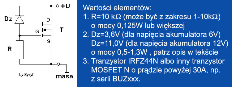
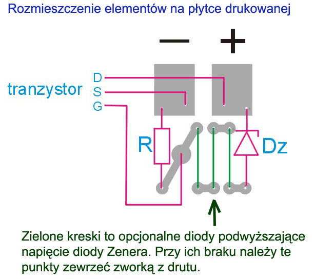
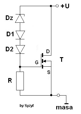
The basic scheme of the system consists only of three elements: the Zener diode Dz, resistor R and MOSFET transistor T, which acts as a controlled resistor:
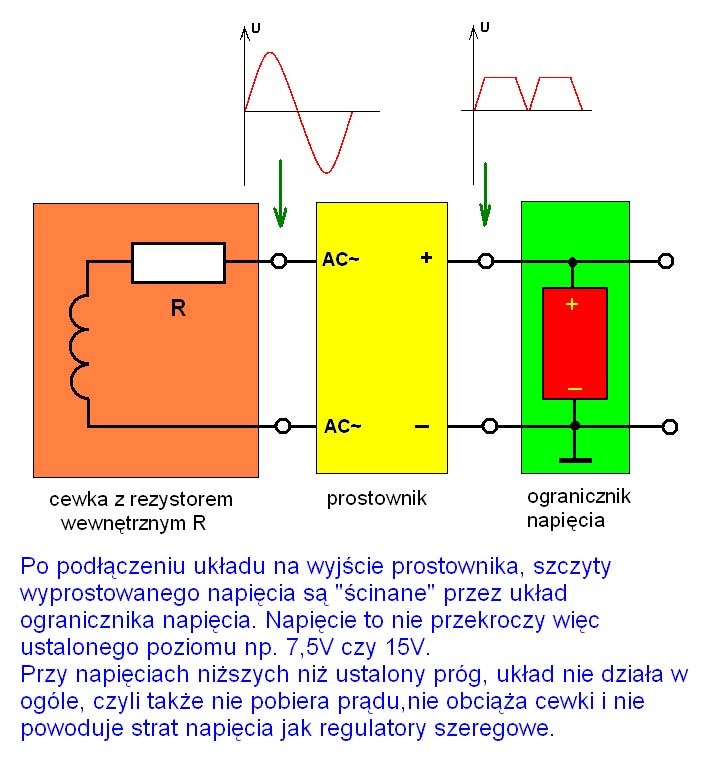
The principle of operation:
The voltage from the rectifier bridge connected directly to the battery is given to terminals “+” and “-”. Once the voltage of the bridges rises above the breakdown voltage of Zener diode Dz, current starts to flow through the resistor, causing a voltage drop on it. The voltage is fed to the gate G of transistor T. Because the voltage on diode Dz is constant, the increase in voltage at the terminals of the module causes an identical increase in voltage on the R. Transistor T becomes conductive when the gate voltage rises above approximately 3,5V and its resistance between the drain D and source S rapidly decreases. That decrease in resistance causes a rapid increase of the current flowing through the T and thus load the charging coil. The voltage at the coil and the voltage across the resistor R decrease, given to the gate G. That lower voltage reduces the transistor T current and reduces the coil load. An equilibrium position will establish, at which the transistor will charge the coil so that the voltage at the input of the system will be on the assumed level, such as 7,5V or 15V.
Thus, the threshold of the system response to the voltage is determined by the voltage of Zener diode. By selecting the voltage, you can easily make the system operate at installation voltage both 6 and 12V. It can also be used for choke (diode) rectifier and then it will reduce the voltage on one half of the rectified voltage.
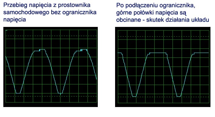
The system “cuts” the upper halves of the rectified voltage at a fixed level.
Installation and start:
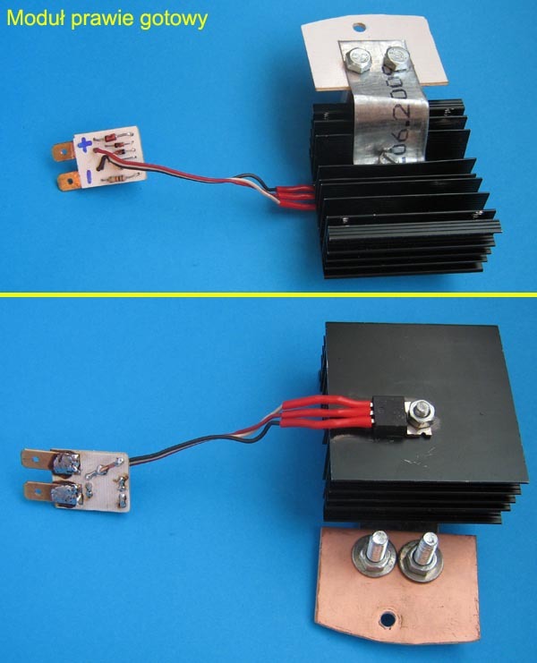
The transistor must be mounted on as large heat sink as possible – in this device, the old PCU heat sink was used.
Below you can see needed elements (there are 2 additional diodes – an explanation is at the end):
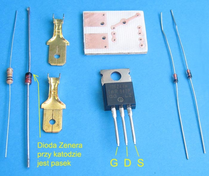

Component, which has a decisive influence on the voltage reduction threshold is the Zener diode. The problem is that you can buy only diodes with a typical voltage range, for example: 3,6V, 5,6V, 10, 11, 12V and no 10,5V. Also transistors have some scatter of the gate voltage, at which they are fully opened (usually about 4V).
If you do not want to fit the system, you can assume that the full opening of the transistor IRFZ44N occurs at 4V and select the Zener diode by the formula: Umax-4V. So, for the maximum threshold 15V (12V accumulator) it will be 11V diode, while for 7,5V (6V accumulator) it will be 3,6V.
The system is really simple, but because of its use (shaking in the vehicle), it is better to assemble it on a PCB. The part that controls the transistor was separated from the transistor because of the heat sink. The board is small 1,8x2,3cm and in addition to the Zener diode and resistor, there are some extra points for connecting 3 LEDs used for any “adjust” the threshold of voltage reduction (description at the end). If you do not need them, just solder the jumper. The transistor is connected with the board by three cables: those for the drain and source should have a slightly larger cross-section: more than 0,5mm in a diameter.
Scheme of the board and distribution of elements:
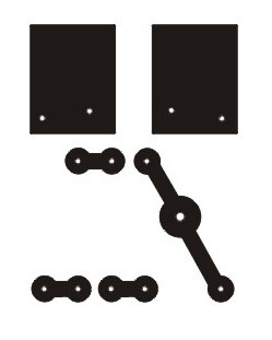
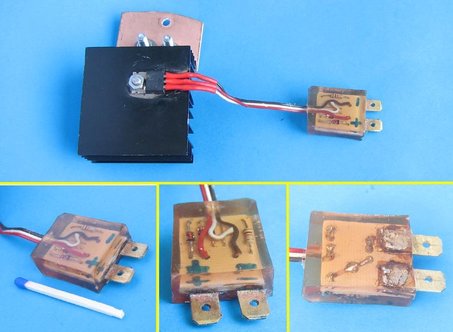
Practical implementation:
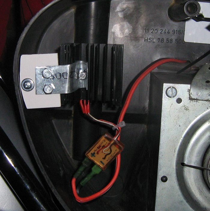
A bracket to attach was screwed to the heat sink in the motorcycle and elements were soldered on the board:
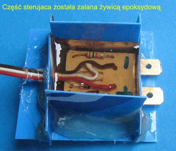
The PCB was flooded with epoxy resin. This protects it against atmospheric influence and the secreted power on the diodes and the resistor and so minimal, that their overheating is not possible.
It looks like that:
Connecting the system in installation:
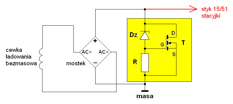
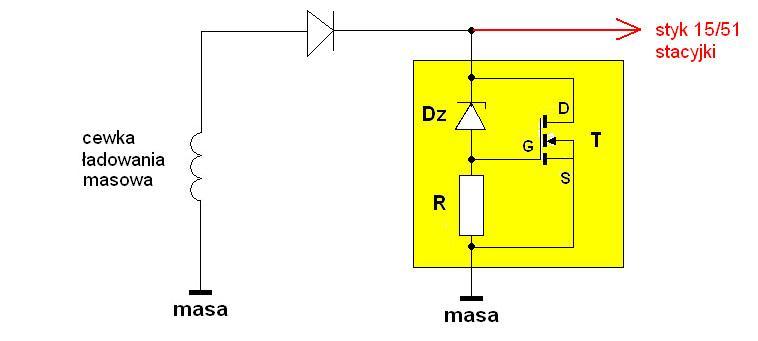
It is best to connect the system behind the ignition and not directly to the accumulator terminals, because it consumes minimum amounts of current at idle, which may cause slight discharging the accumulator. The system can be used either with a rectifier bridge and a single rectifying diode – connect the plus to the plus of the rectifier output and minus to ground.
In this case, plus of the bridge is connected to pin 15/51, on which the voltage from the accumulator appears after turning the ignition switch in position 1 and 2, and therefore this system is connected to pin 15/51.
In the installation with the coil without mass and the bridge:
In the installation with mass coil and rectifying diode:
This system can also be connected with ELBA, if you have it in your installation. The ELBA disadvantage is that it examines only the accumulator charge status and does not affect the voltage level fed to the accumulator. Adding a voltage limiter, you cause better parameters of accumulator charging: it will not be charged with too high voltage, and the ELBA will cut off the charging after the accumulator is in fully charge state. Then the system will also protect the ELBA against excessive voltage that can occur in the contact 59a in the situation of cutting off the accumulator as a coil load, made by the ELBA.
This is the module installed in the Simson clipboard:
Disadvantages and advantages of the system:
The only one disadvantage is additional load of the charging coil in a situation of excess power generated, which can cause damage. Advantages are low cost of elements and simplicity of the construction. It does not require a large interference in the installation: it is connected between the pin 15/51 and mass. In the low turnover range it is neutral for the charging system, turns on only when there is excess power generated.
It is also important to fit the receivers connected to the accumulator. Ideally, if the current generated by the charging coil is partially consumed by fixed receivers, such as the rear light. Then, only a portion of the current from the coil goes to charge the accumulator and the system does not need to take care of the voltage and does not heat too much.
In this case in Simson, all the receivers are connected to the accumulator 12V/5Ah: passing/road light (35W), rear (5W), directions (2x21W), the stop light (21W), horn. The whole is powered by two charging coils with rectifier bridges with “pluses” connected and connected to the ignition pin 15/51 (accumulator plus).
System that prevents from bulbs burn (EWR/ESB1 equivalent):
Light coil is the mass coil (has one detach on mass), and therefore it generates an alternating voltage. You need to connect a rectifier bridge with a current of at least 8A in front of the system, in order to operate the system on both halves. The rules of selecting the Zener diode are the same as described above. Just take into account the voltage drop across the rectifier bridge (about 1,1V). Assuming Umax of the bulb 14V and 1V loss on the bridge, the system must have Umax=13V, so the Zener diode should be at 9V. Also, this system has only two terminals and is connected in parallel to the coil and the bulb:
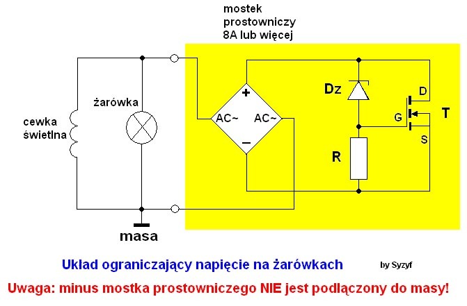
At high speeds, when the peaks of a sinusoidal voltage exceeds a safe level, the voltage limiter that reduces them to a safe level, turns on:
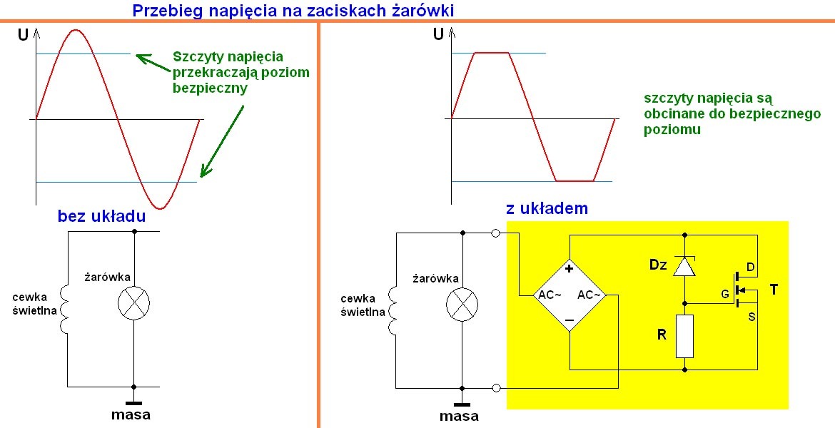
Of course, in incandescent light bulbs, not so much the maximum tension is important, but the effect tension. However, in the case of LED lighting, which has a small inertia, such too high “peak” can burn the LEDs.
Zener diode voltage matching:
If you do not have Zener diode of required voltage or the system cuts off the voltage too low, you may need adjustment and increase the threshold of e.g. 0,5V. The easiest way is to integrate in series with Dz one (or more) different diode (rectifying, pulse, etc.). The LED integrated in the direction of conduction has also constant voltage drop, but much less within the limits of 0,5-1,0V (this can be measured with a meter on the range with the diode symbol – result in mV). So if you connect the Zener diode 10V and 2 “normal” diodes, in the direction of conduction, with the voltage drop 0,6V, we get a replacement diode with “Zener voltage” 10+0,6+0,6=11,2V.
So such a system is created:
We know how to change the voltage of Zener diode, but how to measure to what level the system will limit the voltage, so the Umax.
The easiest way is to connect the module in the installation with accumulator and measure the voltage on it at high speed. Preferably after a few minutes ride so it can charge.
You can connect electrolytic capacitor above 1000uF on the module pins (without accumulator). But here also the meter will not show Umax, because during the descending part of the sine, part of the load will run away from the capacitor during the closing of the transistor. So it will be rather voltage of opening the channel D-S of the transistor. Due to the steepness of the characteristic, it can be assumed that the Umax will be about 0,5V more.
The easiest way to see the waveform on the oscilloscope and determine Umax with its help.
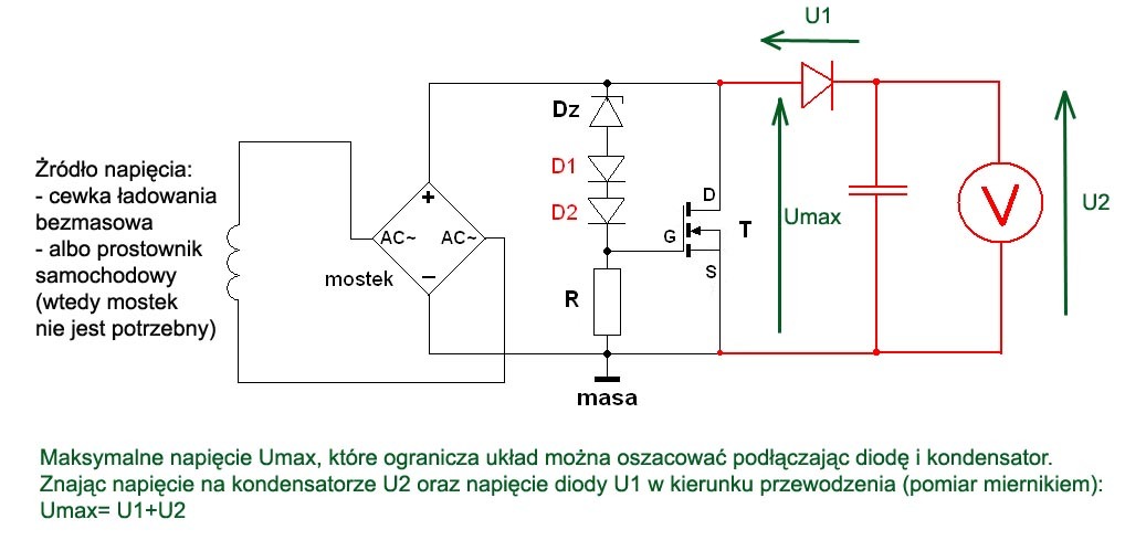
Umax can also be estimated by indirect measurement by the “probe” made of the diode and capacitor above 200nF. Before, you should measure the diode voltage in the direction of conduction, and add this value to the voltage measured by a voltmeter:
Link to original thread (useful attachment) – Układ ładowania akumulatora oraz odpowiednik EWR do Simsona