Continue to Site

Welcome to EDAboard.com

Welcome to our site! EDAboard.com is an international Electronics Discussion Forum focused on EDA software, circuits, schematics, books, theory, papers, asic, pld, 8051, DSP, Network, RF, Analog Design, PCB, Service Manuals... and a whole lot more! To participate you need to register. Registration is free. Click here to register now.

Base current calculation for PNP Transistor BC856

Status
Not open for further replies.

tiwari.sachin

Full Member level 6
Joined
Aug 1, 2009
Messages
341
Helped
3
Reputation
6
Reaction score
3
Trophy points
1,298
Location
India
Activity points
4,449
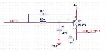
I am using BC856 to drive the backlight of the LCD (positive side switching). The base voltage is 3.3V (Controller IO of LPC2148). Attached is the circuit. I see that the backlight turns ON when IOPIN is low or high ie in both the state BC856 is ON.

Could anyone let me know what might be the error.

The max current required for backlight LED is 30mA and 3.2V is If.

4_1339849319.jpg
 

When IO pin is low, Base current is about 0.00045 Amp due to the 5 V source in emitter. Maybe that could be a possible reason!!!!!!
 

You have the emitter connected to 5v so both 0v and 3v3 to the base will turn the transistor ON (5v-0=5v and 5-3v3=1.7v).
Basically there is no way to turn of the transistor unless you change the emitter voltage or use a second transistor as level translator between the mcu and transistor
 

I did change the emitter voltage to 3.3v and it did work fine... Thanks...

Alexan: Could you let me know how (5v-0=5v and 5-3v3=1.7v) will effect the output. I was just considering current to the base of the transistor.
 

Any voltage difference higher that 0.7v between base and emitter will create a base current and turns on the transistor so it basically translates to base current as you say.
 

I don't see that R63 serves any useful purpose. :?:

It acts as a pull-down so that "LED_SUPPLY" is low, and not floating, when the transistor is off, although it does seem that it should not be required as a floating state would not cause a LED to light up.
 

It acts as a pull-down so that "LED_SUPPLY" is low, and not floating, when the transistor is off, although it does seem that it should not be required as a floating state would not cause a LED to light up.
Yes. It's no different then using an NPN transistor with the LED connected from the collector to the plus voltage. You never see an added resistor in that configuration. All the resistor does is contribute a small amount of wasted current when the transistor is on.
 

R63 is used in the circuit but isnt loaded. It was used to test the initial proto board. Thanks for all your help
 

The transistor will be ON with both 0 or 3.3V at IOPIN. You need to add a base voltage divider to turn it only on with 0 V.
 

Status
Not open for further replies.

Similar threads

Part and Inventory Search

Welcome to EDABoard.com

Sponsor

Back
Top