Continue to Site

Welcome to EDAboard.com

Welcome to our site! EDAboard.com is an international Electronics Discussion Forum focused on EDA software, circuits, schematics, books, theory, papers, asic, pld, 8051, DSP, Network, RF, Analog Design, PCB, Service Manuals... and a whole lot more! To participate you need to register. Registration is free. Click here to register now.

Bad amplifier output

Status
Not open for further replies.

aloishis89

Junior Member level 2
Joined
Jan 8, 2012
Messages
21
Helped
0
Reputation
0
Reaction score
0
Trophy points
1,281
Activity points
1,447
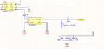
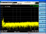
I am using a PSA4-5043+ amplifier in my design and am having trouble getting an output. I attached the relevant portion of my schematic. I am amplifying signals in the range of 500-600 MHz. If I probe the input to the amplifier, I can correctly see my signal, but the output appears to have a large DC component and low frequency harmonics. I attached a screenshot from my spectrum analyzer showing the probed output of the amplifier. I calculated the value of L21 by making it's reactance about 10 times bigger than my system's impedance (50 ohms). The lowest frequency I'll encounter is 470 MHz, so I did:
550j = j*2*pi(470*10^6)L
L = 186 nH
X_L = j*2*pi(100*10^6)(1.86*10^-7) = 117 ohms @ 100 MHz

I can't use the monolithic bias tee minicircuits makes because of budget constraints. Any help figuring this out would be greatly appreciated.
 

Attachments

  • amp schematic.png
    amp schematic.png
    49.5 KB · Views: 81
  • amp output.PNG
    amp output.PNG
    68.3 KB · Views: 73

my spectrum analyzer showing the probed output of the amplifier. I calculated the value of L21 by making it's reactance about 10 times bigger than my system's impedance (50 ohms).
Hi aloishis89
I hope you know your amplifier's out put impedance will be related to the value of XL of that inductor . and as it appears value of your capacitor seems high for that range of frequency . hence that DC component it usual . we have a grate formula to select capacitor to remove DC in our desired range : t/0.4Z hence value your capacitor should be reduced . for preventing some of these problems most of the times these stages will be used as a low power stage and then a buffer or a PA will be added . like a high impedance amplifier . e.g a class C or a simple class E amplifier . but if you select your capacitor properly you won't have any problem .
Best Wishes
Goldsmith
 

Thanks goldsmith. Could you clarify that formula for me? I'm not sure what the 't' is. Also, which capacitor are you referring to as being too large? C80 or the parallel combination of C81, C82, and C83?
 
Last edited:

Yes; the 100nF capacitors C79 & C80 are rather large.

You might also look at L21. Chokes are complex devices and should be tested at the frequencies at which they are proposed to operate.

Just calculating the impedance is not good enough.

See here;

**broken link removed**

and other information that Google will find.

Your L21 will have a SRF at some frequency; if it's close to or below your amplifier's operating frequency it will give problems.

- - - Updated - - -

Sorry; I didn't explain the capacitor value.

A very large capacitor such as you have for C79 & C80 will pass frequencies down to very low frequency; a smaller-value capacitor will act as a crude high-pass filter and limit unwanted lower frequencies entering your amplifier.

Mini Circuits use a rule-of-thumb formula; C (the DC block/coupling capacitor) = 47000pF/Frequency (MHz).

So, for your amplifier's lowest frequency of 470 MHz, C = 47000/470 = 100 pF.


Remember that this is a rule-of-thumb, not a fixed rule, but it works!
 

I have used PSA4-5043+ without problems; I was surprised to achieve noise figure of < 0.5 dB over band.
I observed, however, that some 3V regulators like LP2950CZ-3 generated oscillations and disturbed the operation of those nice LNAs. I had to connect a 10 uF capacitor across the LP terminals to get a clean 3V output.

- - - Updated - - -

The spectrum peaks shown in your picture apparently come from external sources and the ADG device. If you need a clean spectrum, you must use a suitable band-pass filter BEFORE the PSA LNA, and enclose the circuits before it to prevent external FM and local TV signals from getting into PSA. Remember, it is an extremely low noise device. The more sensitive you make the receiver front-end, the more vulnerable it is to interference.
 

Thanks for the help everybody, I really appreciate it. For the inductor, L21, I found one that Coilcraft makes that is 180 nH and has an SRF of 1.08 GHz. Could that work? Since the rest of my system is 50 ohms, the impedance looking in to the amp and bias tee will be different, so would a buffer amp be a good idea there or can I pick capacitor and inductor values that will look like 50 ohms?
 

Thanks goldsmith. Could you clarify that formula for me? I'm not sure what the 't' is. Also, which capacitor are you referring to as being too large? C80 or the parallel combination of C81, C82, and C83?
Hi
Sorry for the delayed answer .
t? t is time ! 1/F !
And about which capacitor my mean is out put capacitor .
Best Wishes
Goldsmith
 

Yes, 180nH with SRF 1G surely can work for 600MHz.
 

Status
Not open for further replies.

Part and Inventory Search

Welcome to EDABoard.com

Sponsor

Back
Top