Continue to Site

Welcome to EDAboard.com

Welcome to our site! EDAboard.com is an international Electronics Discussion Forum focused on EDA software, circuits, schematics, books, theory, papers, asic, pld, 8051, DSP, Network, RF, Analog Design, PCB, Service Manuals... and a whole lot more! To participate you need to register. Registration is free. Click here to register now.

[SOLVED] back to back SCR driver circuit

Status
Not open for further replies.

Alireza12

Newbie
Joined
Apr 4, 2022
Messages
4
Helped
0
Reputation
0
Reaction score
0
Trophy points
1
Activity points
35
Hello guys
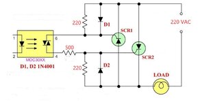
I have used the following image circuit to drive two back-to-back SCR.
A reliable Semicron dual thyristor module has been used for scr1 & scr2 (1000V, 27amp).
and the load is 220 ohm.
when I use this circuit the output voltage is a half-wave because one of the SCRs is not working. ( there is no control current throw the gate)
can anyone help me?
thanks.
Alireza A.
 

Attachments

  • Capture.JPG
    Capture.JPG
    82.2 KB · Views: 444

According to the schematic, it should work. Sure the opto-triac is triggering during both half-waves?
 

Hi,

we miss a lot of information, like:
* mains voltage and load current
* exact SCR type
* drive signal, voltage, current, timing
* a photo of your circuit including wiring / PCB layout
* load type (pure resistive, inductive, capacitive..)
...

every single item maybe can show why it does not work...

Klaus
 

Correct wiring presumed, you may run into problems if the opto triac is ZCD type (304x etc.) and you have either inductive load or distorted mains voltage. A snubber may be required then for reliable triggering at zero crossing.

Specify MOC type and load.
 

My simulation shows SCR2 hampered from turning on, due to load resistance being closer to the gate terminal.

On the chance there are other issues, see if it helps to guide current flow by changing resistor values in your network. Or positions of diodes, etc. In particular, my simulation shows a diode is needed to ensure current enters the gate to turn on the SCR, but not to exit the gate.
 

Hi guys thanks.
I swapped the gate and cathode pins wiring of the scr2 and now it works well.
I don't know why but maybe company's fault.
 

Status
Not open for further replies.

Similar threads

Part and Inventory Search

Welcome to EDABoard.com

Sponsor

Back
Top