sherazi
Banned
- Joined
- Feb 15, 2010
- Messages
- 388
- Helped
- 61
- Reputation
- 126
- Reaction score
- 61
- Trophy points
- 1,318
- Location
- Muscat, Oman, Oman
- Activity points
- 0
regards
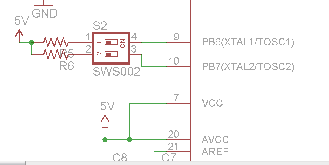
i am using a dip switch to select mode of operation in an var based project...
both on means step mode and if its not 11 then its normal operation..

the concerned code parts are given below
now what so ever i do i get a normal mode... i had even checked voltage at the pins of avr using DMM... plz point out whats wrong?
i am using a dip switch to select mode of operation in an var based project...
both on means step mode and if its not 11 then its normal operation..
the concerned code parts are given below
Code:
DDRB = 0x3E;		//	port b is output except PB0, PB6 and PB7
PORTB =0X00;
Code:
b=PINB;
	b|=0x3F;
	if(b=0xff) //means step mode
	{
		goto step_full_open;
	}
        else goto normal_mode;
now what so ever i do i get a normal mode... i had even checked voltage at the pins of avr using DMM... plz point out whats wrong?