Continue to Site

Welcome to EDAboard.com

Welcome to our site! EDAboard.com is an international Electronics Discussion Forum focused on EDA software, circuits, schematics, books, theory, papers, asic, pld, 8051, DSP, Network, RF, Analog Design, PCB, Service Manuals... and a whole lot more! To participate you need to register. Registration is free. Click here to register now.

Audio Circuit Problem

Status
Not open for further replies.

Nirodha

Newbie level 6
Joined
Jan 29, 2010
Messages
11
Helped
0
Reputation
0
Reaction score
0
Trophy points
1,281
Activity points
1,389
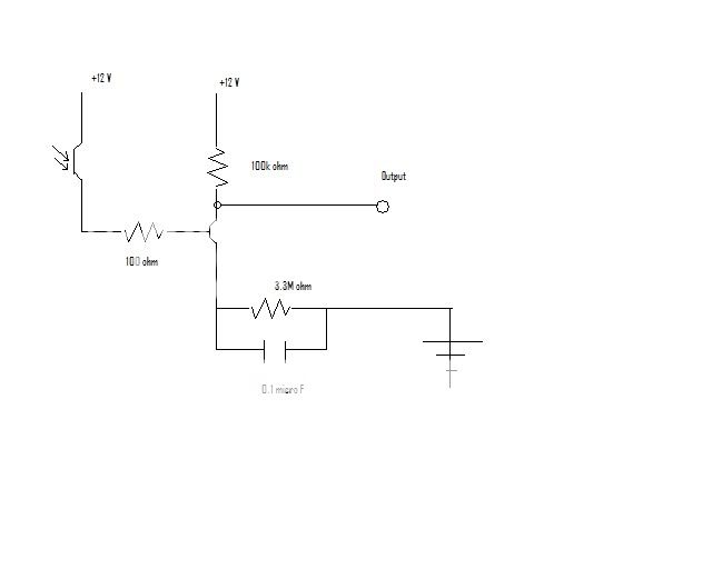
I'm building a laser microphone for my senior project. The idea is to bounce a laser off a reflective surface, capture the reflected beam with a photo-transistor, then convert the signal into sound. Vibrations in the glass from a voice will modulate the laser signal, and the voice should come out on the other side.

When I use a simple transistor amplifier circuit and connect the output to my laptop computer, it records pretty well; I can record myself talking at the piece of glass.

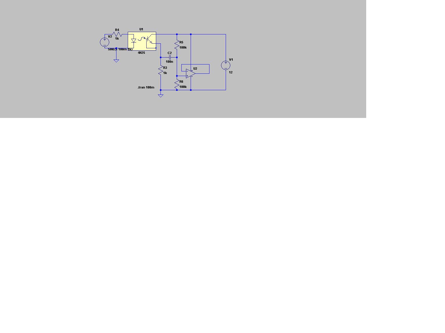
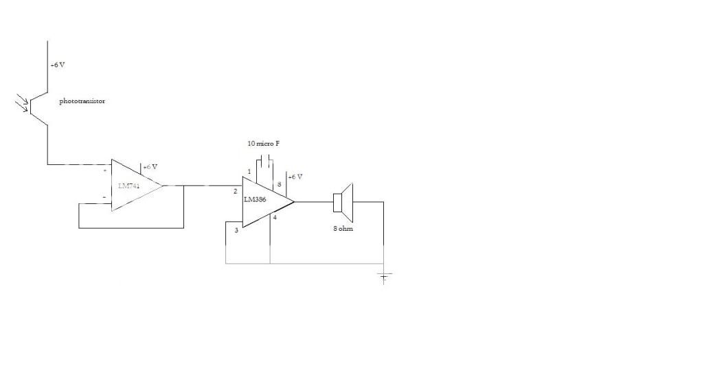
When I try moving the output to a 9V speaker/amp from Radioshack, the output disappears. I tried removing my amplification step entirely, I tried a LM386 low voltage audio amp, I tried an Op-Amp, and nothing is working.

My advisor didn't look at my circuit, but told me I have an impedance matching problem, so I'm not driving the speaker properly. I don't really know how to measure impedance, or where in the circuit to measure it.

Is this really my problem? If so, how can I effectively measure the appropriate values and fix them? If not, any ideas?

Any ideas or suggestions are much appreciated.
 

Try using an op-amp as a buffer(very high input impedance) and then your LM386/other options after that. That will rule out loading due to having too low an input impedance.
 

sorry... posted something without knowing much....
 

This is not RF. You don't match speakers to the output of your amp.
The output of an lm386 is probable fractions of a ohm.
He may well be loading his phototransistor cct with to low an impedance , that is why it works with the laptop(mic input may be quite a high input impedance),
but not otherwise. Use a "buffer" between the photo cct and the power amp to stop the loading of the power amp on the photo transistor cct.
 

That would be helpful , and limit some of the guesswork :0)
 

try using an 8 ohm to 600 ohm audio transformer.
the audio output may be a little noisy but may work.
just an idea

steve
 

Ok, here is the circuit as it worked using the laptop as an output. The goal is to get it to work with a speaker. Right now, I have the speaker/amplifier from Radioshack, but I can buy a simple X-ohm speaker easily enough if that simplifies the problem.

workingcircuit.jpg
 

Is that resistor really 3.3M ohm? If so, it is surprising that it does anything at all.

Keith.
 

Yeah, it is. I increased the resistance on that resistor slowly, and each time it improved the gain of the circuit (with the laptop as output). I was surprised to find it functioned best with that large resistance, but that may mean that the amplifying transistor component isn't doing exactly what I think it's doing.

I'm sure some better circuit can be constructed, and the project isn't really any good if I can't get it to produce sound in a speaker (the laptop was just for testing).
 

Nirodha said:
Yeah, it is. I increased the resistance on that resistor slowly, and each time it improved the gain of the circuit (with the laptop as output). I was surprised to find it functioned best with that large resistance, but that may mean that the amplifying transistor component isn't doing exactly what I think it's doing.

I'm sure some better circuit can be constructed, and the project isn't really any good if I can't get it to produce sound in a speaker (the laptop was just for testing).

Dear, that looks you have a serious BJT bias problems!!.......you will need to calculate the bias point and verify that amplifier is in the rigth Q point. Which one BJT are using??...What is the Base Q Current???.....How many miliamperes is flowing from the Phototransistor to the BJT Base???....

This BJT could to be in saturation all the time or no amplification at all maybe!!

Opacheco.
 

Apart from the obvious biasing problem , the output impedance of your cct is way to
high. Connecting even a modest load will kill any signal that may be present.
Use an opamp as a buffer. I'm going to try an attach a picture , but I'm new here so I'm not sure if it will work. Any jellybean opamp (lm324 , lm358 ) will work for your application :0) Their are obviously better opamps , but these are common as dirt :0)
Connect your lm386 audio power amp after the opamp.I used a 4n24 just to mimic your photo-transistror.

 
Last edited by a moderator:

Well, I put together the circuit using some suggestions you guys made:

circuit.jpg


I got some static to come out of the speaker, but still no luck overall. The LM386 component is getting a little bit warm. Did I miss a component?

Thanks[/img]
 

If you have drawn the cct exactly as you have built it , you are going to have problems with the LM386. Check the datasheet.
First problem is the speaker is connected directly to the ic. It should have a decoupling capacitor(say 220uF).With the current configuration you ase going to have 375mA flowing through the speaker all the time(assuming 8 ohm speaker). No wonder the 386 is getting hot!!!
Once again check the datasheet.Signal into pin 3 , pin 2 grounded.
I've attached the datasheet :0)
 

Basically a good news: You're neighbours don't have to fear eaves dropping at the present project state. :D
 

The question title is misleading, the actual project challenge is optics, not a trivial audio amplifier circuit. For the vibrations
to detect, you can assume a nanometer order of magnitude. The method is known to work - with special instrumentation.
 

He did say that he had it working with a laptop though , so I assume he's on the right track.
The fact that he got the first part of the project (optics etc) working is surprising though :0)
 

Use a single supply op-amp , like the Lm358,lm324. Not the best , but will work for this application.
 

Status
Not open for further replies.

Similar threads

Part and Inventory Search

Welcome to EDABoard.com

Sponsor

Back
Top