Continue to Site

Welcome to EDAboard.com

Welcome to our site! EDAboard.com is an international Electronics Discussion Forum focused on EDA software, circuits, schematics, books, theory, papers, asic, pld, 8051, DSP, Network, RF, Analog Design, PCB, Service Manuals... and a whole lot more! To participate you need to register. Registration is free. Click here to register now.

[SOLVED] Arduino Based 500VAC Voltmeter - 3.3Vin

Status
Not open for further replies.

kokhoor

Newbie
Joined
Aug 29, 2020
Messages
4
Helped
0
Reputation
0
Reaction score
0
Trophy points
1
Activity points
39
Hi,

I went thru this article and plan to build it: https://www.engineersgarage.com/contributions/arduino-based-voltmeter/

I will only be building the 500VAC part. However, I am planning on using NodeMCU ESP8266 or ESP32, which is only 3.3V

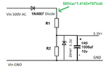
In this case, what should I change to the diagram? I was advised on diagram below, but I think it will then block off the higher voltages preventing full measure. Should I instead change to different resistors?
Measure500V.png


Hope someone can advise.

Thanks.
--- Updated ---

My calculation seems to indicate, if I don't add the Zener Diode, I can try:

R1 = 1000000
R2 = 6600

Because:
R1 / R2 = 151.515115
(500V / 3.3V) - 1 = 150.515115

The part I don't understand is the W required for the resistors, so I plan to stick to 0.25W

Do these numbers look correct?

Thanks.
 
Last edited:

That is a strange way to connect the zener. I presume you want a stable voltage source for the arduino, right? Within a current range, the zener is supposed to maintain a reasonably stable voltage across its terminal. Please explain your idea.
 

1N4148 will die due to excess reverse voltage, use something like a 1N4007 instead.
The 1M resistor should be rated for much higher than the AC peak of about 710V. Several resistors in series would be safer.
The Zener does nothing useful at all. If it is supposed to provide over voltage protection it should across the 10K.
Bear in mind that the ESP8266 and ESP32 cannot tolerate negative voltages at their inputs.
Also, depending on which module or IC you uses, some cannot accept more than 1V at their inputs.

Calculate the resistor divider so it drops the PEAK (1.414 * RMS if it is a sine wave) down to whatever the measurement input can accept and for protection it would be far safer to use two Schottky diodes, one from the input to ground and one from the input to 3.3V to clamp negative and excess positive voltages.

Also note that the ESP32 ADC is a bit weird at low and high ends of it's measurement range. Its output flattens below about 0.2V and above about 3.1V so if that's the device you use it would be wise to keep the divider voltage nearer mid range.

Use Ohms law to work out the resistor power ratings but as mentioned earlier, watch for the maximum voltage the top end resistor is rated at.

Brian.
 
6600 is not a standard resistor value
6650 is, and using 6650 with the 1 Meg yields 3.3V, so you need to check the maximum input value of your processor

get a table of standard resistor values

at 500 V, the power drop across the 1 Meg resistor is 1/4 W. use a 1/2 watt instead
when things are working properly, the 6650 ohm resistor will see no more than 3.3V, so 1/4 is plenty. (you could go down to 1/10W)

I do not see the zener diode anywhere in the engineer's garage link you provided
i don't think it helps your device in that configuration

the program assumes sinusoidal AC to convert from peak voltage to RMS voltage
if the signal is not sinusoidal, you will not get the correct RMS voltage

the DC voltage is calculated from the maximum of 5000 samples (measuring DC Voltage)
it may be better to take the average of the 5000 samples

my guesstimate of the tolerance of the circuit is 2 to 3 %, assuming you use 1% resistors
this does not include tolerance in the ADC.

i did not go through the program
it looks like the photograph of the breadboard has more stuff than the project
 
So you want to make a voltmeter. First thing first: define the specs.

Say the input voltage will be 300-700V AC and you want only the RMS or the peak value.

Further assume that the frequency is not too high, say around 30-100Hz.

Say your zener is 1/2W; so you use a dropping resistor (in series) and a capacitor in parallel with the zener. The zener can take upto 150 mA. The zener may not work below 1mA and your arduino may need around 10mA or more. Decide the series resistor based on the current and power ratings. Calculate the current at both ends of the voltage.

Use a full wave bridge rectifier with a small inductor and a capacitor. Calculate the voltage divider for the low end and the high end of the voltage.

You may select 1V full scale for the A/D converter and feed 300-700 mV to the input. Hence the voltage divider should be 1000 to 1 (you need to consider the peak values).
 
Hi,

The most precise method is:
HV_input
Series RC to ADC_input, C from ADC_input to GND, R from ADC_input to V_ADC_range/2.
The first C is for blocking DC, the second C is a low pass filter.
Simple hardware: 2(3) R, 2 C

It can measure AC without additional distortions and without additional unlinearities (diodes). It can't measure DC.

But you need a constant known sampling rate and RMS calculation software. Best done within an ISR.
Then you get perfect RMS values, independent of waveform...up to a some overtones, depending on sampling rate and LPF.

Klaus
 
In this method, you want to make a 3.3 volt power supply, you can not have much current at 3.3 volts. Because you will have both power losses and the voltage of 3.3 volts will not remain constant.

The zener diode should be placed in parallel, and for a smooth voltage it is best to install a capacitor parallel to the zener diode.
(The diode that you put in series prevents the voltage from passing to the output if the voltage dividing the resistors is less than 3.3 volts. That is, it prevents voltages less than 3.3 volts.)

Use the input diode as your friends said 4007 or bridge the diode.
Zener diode power and resistors depend on the minimum and maximum current consumption.

Also, your input voltage will increase after the diode. With one diode it becomes 500 * 1.4142 = 707 volts. So recalculate the resistance values. (It is better to design the values for more than 3.3 volts so that the zener diode stabilizes it to 3.3 volts. For example, 4 volts)

Also note that not all 3.3 zener diodes can produce an accurate voltage of 3.3 volts. This means that this power supply does not always give you a constant 3.3 volts.
So you have to test it first.
I recommend the following circuit for low current consumption. (Same as your circuit and friends analysis)

S.rezapoor
 

Attachments

  • c.png
    c.png
    23.3 KB · Views: 161

question:
is the goal to build the project ?
are you going to devote the project to be a voltmeter ?

if you're looking for a meter, try this:
https://www.fluke.com/en-us/product/electrical-testing/digital-multimeters/fluke-116#
or

multimeter is more expensive than the project, but it does a lot more, and you can depend on it
 

Wow, so much input. Thanks and appreciate it everyone! I'll go thru and see which is best option to use. Again, thanks!
--- Updated ---

Hi Klaus,

It will be great if you can help to provide a diagram for this to make it clearer.

Thanks.

Regards,
Kok Hoor

Hi,

The most precise method is:
HV_input
Series RC to ADC_input, C from ADC_input to GND, R from ADC_input to V_ADC_range/2.
The first C is for blocking DC, the second C is a low pass filter.
Simple hardware: 2(3) R, 2 C

It can measure AC without additional distortions and without additional unlinearities (diodes). It can't measure DC.

But you need a constant known sampling rate and RMS calculation software. Best done within an ISR.
Then you get perfect RMS values, independent of waveform...up to a some overtones, depending on sampling rate and LPF.

Klaus
--- Updated ---

Hi,

I need input into an Arduino (ESP8266 or ESP32) to capture the data and send over Internet, therefore, not able to use a digital multimeter.

Thanks for your reply!

Regards,
Kok Hoor

question:
is the goal to build the project ?
are you going to devote the project to be a voltmeter ?

if you're looking for a meter, try this:
https://www.fluke.com/en-us/product/electrical-testing/digital-multimeters/fluke-116#
or

multimeter is more expensive than the project, but it does a lot more, and you can depend on it
--- Updated ---

6600 is not a standard resistor value
6650 is, and using 6650 with the 1 Meg yields 3.3V, so you need to check the maximum input value of your processor

get a table of standard resistor values

at 500 V, the power drop across the 1 Meg resistor is 1/4 W. use a 1/2 watt instead
when things are working properly, the 6650 ohm resistor will see no more than 3.3V, so 1/4 is plenty. (you could go down to 1/10W)

I do not see the zener diode anywhere in the engineer's garage link you provided
i don't think it helps your device in that configuration

the program assumes sinusoidal AC to convert from peak voltage to RMS voltage
if the signal is not sinusoidal, you will not get the correct RMS voltage

the DC voltage is calculated from the maximum of 5000 samples (measuring DC Voltage)
it may be better to take the average of the 5000 samples

my guesstimate of the tolerance of the circuit is 2 to 3 %, assuming you use 1% resistors
this does not include tolerance in the ADC.

i did not go through the program
it looks like the photograph of the breadboard has more stuff than the project

Hi wwfeldman,

If I am to use a 1/2 W for the 1MOhm and 1/4W for the 6650 Ohm, will my P = V / R calculation be impacted and therefore need to use a lower ohm resistor?

Thanks.

Regards,
Kok Hoor
 
Last edited:

If I am to use a 1/2 W for the 1MOhm and 1/4W for the 6650 Ohm, will my P = V / R calculation be impacted and therefore need to use a lower ohm resistor?

no
the power rating of the resistor does not change the required resistance
the required resistance is determined by the needs of the circuit
the power dissipated by the resistor is also determined by the needs of the circuit
the required power rating has to be bigger than the power dissipated
 
no
the power rating of the resistor does not change the required resistance
the required resistance is determined by the needs of the circuit
the power dissipated by the resistor is also determined by the needs of the circuit
the required power rating has to be bigger than the power dissipated

Hi Feldman,

Thanks for your reply. Hope you can help to explain more.

I was thinking for the 1 Megaohm resistor, the formula I used to obtain it is calculated in the formula below, P is the resistor rating. If it isn't the case, where do I get P?

P = (V*V) / R

Thanks.

Regards,
Kok Hoor
 

Hi Feldman,

Thanks for your reply. Hope you can help to explain more.

I was thinking for the 1 Megaohm resistor, the formula I used to obtain it is calculated in the formula below, P is the resistor rating. If it isn't the case, where do I get P?

P = (V*V) / R

Thanks.

Regards,
Kok Hoor
Hi

There are three ways to calculate power:
P=V*V/R
P=R*I*I
P=V*I
You can use the P=V*V/R formula.

To calculate the power rating of a 100 kohm resistor at a voltage of 100 V:
100 volts * 100 volts / 100 kohm = 0.1 watts.
That means you have to provide a resistance of 100 kohm with at least 0.25 watts. (We do not have 0.10 watt resistance)

But if your voltage is 1000:
1000 volts * 1000 volts / 100 kohm = 10 watts.
The resistance here is the same as 100 kohm, but of the type of at least 10 watts.
The size of a 10 watt resistor is much larger than 0.25 watts.

For resistance, the two characteristics ohm and watt are defined separately.
 
very good Reza

@kokhoor
the P in the equation (all three Reza posted) is the calculated dissipation
the power rating of the resistor to use has to be greater

a good approximation is 50% larger - so whatever the calculated
dissipation is, multiply it by 1.5 and use the next larger resistor power rating.

a calculated 0.1 W, times 1.5 is 0.15 W - since the next larger standard power rating 0.250 W, use that
 
Hi,

... and back to your 100V / 1000V example:
You always need to calculate with the highest power value.
Means: the power dissipation at 100V is not of interest if you know you want to measure up to 1000V.

Klaus
 
Hi all,

Thanks for all the input. I settled for a solution like below, constantly measuring to fine tune the R2 resistor required.

This may not be a good / accurate solution, but is good enough for me to produce an alert when the value fluctuates out of range.

Thanks, everyone!

Regards,
Kok Hoor

1599272775203.png
 

Hi,

Fine tune... why ?
A simple multiplication in the software is less effort, stable, no drift....

Klaus
 

Status
Not open for further replies.

Part and Inventory Search

Welcome to EDABoard.com

Sponsor

Back
Top