Continue to Site

Welcome to EDAboard.com

Welcome to our site! EDAboard.com is an international Electronics Discussion Forum focused on EDA software, circuits, schematics, books, theory, papers, asic, pld, 8051, DSP, Network, RF, Analog Design, PCB, Service Manuals... and a whole lot more! To participate you need to register. Registration is free. Click here to register now.

Analog linear Voltage level converter

Status
Not open for further replies.

hameeds01

Advanced Member level 2
Joined
Aug 23, 2005
Messages
599
Helped
75
Reputation
156
Reaction score
41
Trophy points
1,308
Location
Islamabad Pakistan
Activity points
4,540
Hi guys!

I want to know how to convert the analog voltage level range (-3v to +3v) to analog voltage level range (0v to 5v)

(-3v to +3v) Input -------> CONVERTER --------> (0v to 5v) Output
 

Hi All

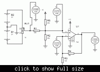
You could try this as a start point.

Best Francisco
 

Attachments

  • Edaboard2.pdf
    19.1 KB · Views: 155

Try using the circuit I posted - it works!

Keith

yeah ur Circuit is working perfect Thankx but i want to know the formulas how u calculate that ?? secondly ur circuit needs lots of supplies (+15v, -15v & -3v)

now my requirements have changed, i want (-4v to +4v) to (0v to +5v) ??
 

You can use +/-5V instead of +/-15V but you need to find an opamp that works well to the positive rail. You could even use a single +5V supply by moving the offset -3V to the non-inverting side and using a positive voltage, but then you need an opamp with good rail to rail performance. A lot of rail to rail opamps tend to tail off at the extremes.

The -3V can be replaced with a could of resistors between the rails. You just need to ensure that the parallel combination of the potential divider is the same as the resistor it would replace. See attached.

I have also attached a single supply version, although it could probably do with a better choice of opamp - I just picked one at random.

The circuit is based on the standard differential amplifier which should be in most books. To select the resistors (or at least the ratios) you first need the gain. In you case you are trying to change +/-3V = 6V into 5V so the ratio is 6/5. So the resistors should be in that ratio. I showed 12k & 10k but you could use other combinations.

The -3V is simply because you want to shift -3V to 3V to start at 0V so your input voltage is relative to -3V.

To use a potential divider instead of a -3V supply, as I have shown, you need to keep the same total resistance while providing -3V. So, you want -3V from -5V so the resistors need to be in the ratio 3/2 (3V across one resistor, 2V across the other). The resistor you are replacing is 12k so the two resistors in parallel need to be 12k. A bit of equation juggling and you find 20k and 30k satisfies both requirements.

If you want to do the shift from a positive voltage so you can use a single supply opamp then you put the resistors on the non-inverting input, as shown. However, now the resistor needs to replace 10k and the shift is 2.5V not 3V because the shift is occurring after the scaling of the input voltage by 5/6. So, 20k and 20k satisfies those requirements.

Hopefully that should help you re-calculate for the -4V/4V requirement.

Keith.
 

Attachments

  • Level shift no -3V.pdf
    8.2 KB · Views: 133
  • Level shift single supply.pdf
    8.5 KB · Views: 149
Hi all

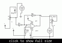
I have this working in Proteus 7.7.This circuit generates an output of 0 to -5v.Put an inverter in the output.........
Of course it may need some litle adjustments in the resistor values, and a fet input opamp like like CA3140, and an offset adjust to work in the real world.It is not a final project it is just a simple idea.

Best Francisco
 

Francisco,

I think your circuit is similar to the one I posted "Level shift single supply.pdf" with the following differences:

1. I have balanced the impedances on the two inputs for best noise immunity and to minimise bias current errors,
2. the output of my circuit is the correct way round without extra inverters,
3. the method I have outlined allow direct calculation of the component values - no adjustment is required,
4. it won't need an offset adjust with a decent opamp and the correct component values.

Keith.
 

Hi Keith.
I agree with , great circuit.
I´ve just implemented a real circuit and it works like a charm.
I´ve replaced LM741( I don´t have one) by Ca3140 and +/-3 by +/-5.
SO the circuit works.

By the way, do you know anyone that could help me in my thread https://www.edaboard.com/threads/185777/

BEst Francisco
 

I did make a pdf for this purpose. You use a regular non-inverting amplifier. Note that ground potentional isn't always 0 volts.

It was made for me to read, so I haven't spend much time for a eloquent explanation :smile:
 

Attachments

  • nonInvert_en.pdf
    88.2 KB · Views: 128

The reason you need to use a differential amplifier is to have a gain less than unity. With a non-inverting opamp circuit the minimum gain is unity. The initial requirement is for a "gain" of 5/6. The latest requirement is for 5/8 which also needs a differential amplifier so you can have a gain less than unity. Looked at another way, it is a non-inverting opamp with an attenuator on the non-inverting input!

Keith.
 

@ Keith
Respected Sir

Can u plz give me the formulas how u did that ?

---------- Post added at 21:20 ---------- Previous post was at 21:06 ----------

dude there is a DC bias at -3v input


---------- Post added at 21:21 ---------- Previous post was at 21:20 ----------


[/COLOR]dude there is a DC bias at -3v input


---------- Post added at 21:21 ---------- Previous post was at 21:20 ----------


That is because you are using a 741 with no negative supply (i.e. using ground/0V). The 741 cannot drive down to 0V. If you want to use a single supply then you need an opamp that can drive down to its negative rail. That is why I picked the MAX4250 - it has a rail to rail output although it can onlybe powered from 5V, not 12V.

keith.
 

@ Keith
sir now my demand has changed
i need to converter (-4v to +4V) to (0v to 5v)

(-4v to +4V) -----> CONVERTER -----> (0v to 5v)
 

In which case you just need to change the gain to 5/8 instead of 5/6. The two 20k resistors to +5V and GND stay the same because the 10k stays the same and the shift in level (-4V rather than -3V) occurs after the attenuation.

Keith.
 

Attachments

  • Level shift +-4V.pdf
    8.7 KB · Views: 121

great thread!! very helpful..
 

@ keith1200rs

sir how to convert the analog voltage level range (+3.3v to +3.7v) to analog voltage level range (0v to 5v)

(+3.3v to +3.7v) Input -------> CONVERTER --------> (0v to 5v) Output
 

Hi.

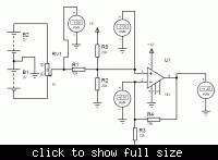
Converting (+3.3v to +3.7v) Input -------> CONVERTER --------> (0v to 5v):

1: DC amplification = ΔUut/ΔUin = 5V/0,4V = 12,5 times.
2: Need to adds up with 3.3V.

That make it possible to achieve it several ways:
1* Differential amplifier with a gain of 12,5, and negative input being fixed to 3.3V
**broken link removed** :wink:

2* Instrumentation amplifier with amplification set to 12,5. The ground terminal AND negative input both set to 3.3V fixed voltage. This is posible the most stable amplifier solution, but also takes more number of components - unless you can buy one-chip instrumental amplifier instead of three separate opamps.

3* Using a transistor solution. Downside here is that it takes more calculation to fine-tune amplification, AND is possible the most unstable solution due to drift in transistors conductive properties over time.
This can be made up in many different ways, depending of type of transistor you want to use and what voltage suplies that is avaiable.
 
Last edited:

Status
Not open for further replies.

Similar threads

Part and Inventory Search

Welcome to EDABoard.com

Sponsor

Back
Top