Continue to Site

Welcome to EDAboard.com

Welcome to our site! EDAboard.com is an international Electronics Discussion Forum focused on EDA software, circuits, schematics, books, theory, papers, asic, pld, 8051, DSP, Network, RF, Analog Design, PCB, Service Manuals... and a whole lot more! To participate you need to register. Registration is free. Click here to register now.

Analog IC design project.....help plz

Status
Not open for further replies.

ak214

Junior Member level 3
Joined
Mar 6, 2006
Messages
28
Helped
0
Reputation
0
Reaction score
0
Trophy points
1,281
Location
India
Activity points
1,567
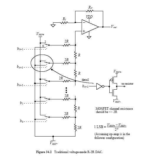
Design a voltage mode R-2R DIGITAL TO ANALOG CONVERTER which is 10 bit accurate to with in 0.5 LSB over its full scale range. The values are R=10k, Operating at clock frequency >=10 MHz and drives a capacitive load of 10pF.


Read theory of this DAC. Understand characterizing parameters. Derive the specifications for OPAMP , resistors and switches to be used..

Can any one give idea of how to design the circuit according to the specs given above.....
 

hi!

do you need this in full layout? or just schematic? or even simpler just hand calculated? maybe if i know the final requirement i might be able to help.

- al
 

you can give schematic along wid ... necessary mathematical calculations... thx in advance.
 

hi!

i mean do you have to put sizes on the inverters? or do you need to design your own op amp? what exactly are the components that you need to design? do you need a specific op amp gain, badwidth, etc... ?

- al
 

I ve to design opamp aswell as inverters also... and i have calculated the gain according to given specs as 4096 and also unity gain BW. I ve to also design the current reference circuit. can u give W/L (design) of each opamp
thank u

Added after 2 hours 56 minutes:

i have calculated gain as 4096 and unity gain freq 24.2Mhz according to the book BAKER(cmos design). i assumed a slew rate .1V/10ns and calculated the bias current 1000uA. and i designed tthe opamp acc to this. i m sending the circuit. can u plz tell me how to design the bias ckt for bias current of 1000uA. and also the inverter circuit.
 

hope this help....in your quest designing your own op amp...

this website might be of help..**broken link removed**
 

Status
Not open for further replies.

Part and Inventory Search

Welcome to EDABoard.com

Sponsor

Back
Top