Continue to Site

Welcome to EDAboard.com

Welcome to our site! EDAboard.com is an international Electronics Discussion Forum focused on EDA software, circuits, schematics, books, theory, papers, asic, pld, 8051, DSP, Network, RF, Analog Design, PCB, Service Manuals... and a whole lot more! To participate you need to register. Registration is free. Click here to register now.

Analog electronics book with circuit explainations

Status
Not open for further replies.

vreg

Member level 4
Joined
Oct 16, 2012
Messages
70
Helped
1
Reputation
2
Reaction score
1
Trophy points
1,288
Activity points
1,935
Hi,
Is there any book on analog electronics that gives good circuit examples with explanations of each component. I'm looking for something with practical circuit examples and not just concepts. Like why that particular capacitor is included in the circuit- most books just explain the main components and don't explain why all the other components are there...

Thanks.
 

The best way to learn is start with the characteristics of each component. Fortunately each component can be modeled with network of other passive combinations of RLC. Construction of the conductor and dielectric qualities are what makes the millions of different capacitors and their designs different using a dozen basic material ( ceramic, plastic films, tantalum, Alum electr, paper, mica etc ) types to fulfill hundreds of different application requirements.

For high current, ESR or effective Series Resistance, is critical which also affects the rated rms ripple current and the peak surge current and feedback voltage sensed in feedback SMPS circuits. The range of ESR affects the gain, and stability of feedback loops.

For RF, the ESL or Effective Series Inductance, is critical which is often specified by the Series Resonant Frequency, SRF. ( often called Self Res. Freq) and in Microwave there are also important impedance modes for the Parallel Resonance Frequency or PRF and often simply characterized by a full matrix table of S parameters.

For low leakage current integrator or Sample & Holds or long time constants, a high parallel resistance or Self discharge time constant is important.

For high voltage applications, dielectric strength, self-healing characteristics and fail safe modes and safety agency approvals are critical and labelled by line to line or line to ground etc by different class levels such as X1,X2,X3 and Y1,Y2,Y3.

It is important to remember all insulators are dielectrics and there is always trade-off between each of the parameters such as cost, size, voltage rating, ripple current, ESR, SRF, temperature rating, temperature coefficient, voltage stability, polarization effects, microphonic effects, memory effects.

Lifetime is significantly degraded when a design uses the the capability that results in thermal stress or breakdown stress or any type of stress, so margins must be considered and everything derated conservatively.

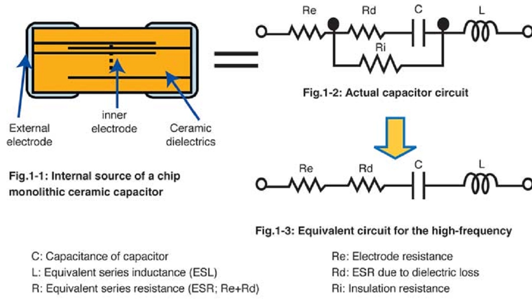
For example here is the equivalent circuit of a ceramic cap.
5957558300_1419810553.jpg
 
The Art of Electronics by Horowitz and Hill (the one with the silver cover, not the black one) is generally accepted to be the beginner's Bible
 

This is how I began. By learning the properties of real parts then it made sense why each type is used.

Then reading application notes from National Semi, now TI on how Linear and digital parts work. I read every designer's notes in EDN magazines with the theory of operation to understand how designs work.

E.g. **broken link removed**
 

Status
Not open for further replies.

Similar threads

Part and Inventory Search

Welcome to EDABoard.com

Sponsor

Back
Top