Continue to Site

Welcome to EDAboard.com

Welcome to our site! EDAboard.com is an international Electronics Discussion Forum focused on EDA software, circuits, schematics, books, theory, papers, asic, pld, 8051, DSP, Network, RF, Analog Design, PCB, Service Manuals... and a whole lot more! To participate you need to register. Registration is free. Click here to register now.

Analog circuit that controls valves for water flow

Status
Not open for further replies.

www111

Junior Member level 3
Joined
Oct 10, 2012
Messages
29
Helped
0
Reputation
0
Reaction score
0
Trophy points
1,281
Activity points
1,541
Dear all,

I'm trying to design some analog circuit for water vale control, here is the simple block schematic:
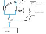
Valve.jpg

So the idea is:

we have two independent sources of water and one tank and we want to fill the tank.

First we supply the water trough valve1 and measuring the water pressure in tank with the sensor and compare to a reference ( eg. if the pressure is below 1bar) then we close the valve1 and open the valve2 and give the trigger to timer delay circuit ( 12h delay) and after the delay expires the output of timer circuit closes the vlave2 and opens the valve1. This have to work in loop.

How can I design the analog timer delay circuit and the compactor, what IC should i choose for compactor and the timer delay circuit ?

This circuit can work with 5VDC or 12VDC or 24VDC.

I need to chose the latching solenoid valve and relay for the valve. Do you have any recommendation for the valve and the relay?

valve has to be 1" 4bar max pressure.

Thanks for help.

Best Regards.
 

Hi,

Valve option:
 

Attachments

  • Soleniod Valve 12VDC 1cm Threaded or Pushfit inlet outlet.pdf
    161.4 KB · Views: 52

Hi,

Valve option:

I was looking at the latching solenoid valve but they are expensive.
Do you maybe know some cheaper latching solenoid valve?

also here is one non latching
**broken link removed**

If my calculation are correct and using two of them it will consume 90kWh in one year.

Best Regards.
 

1" direct operated valve needs quite strong drive. For lowest power consumption, a motor operated three-way ball valve might be considered.
 

Hi,

Isn't this a job for a small, cheap PLC?

Klaus
 

Trying to circumscribe the issue as a whole, it is something curious that the command for the first switching of the valves is done with a closed loop control by measuring the water level of the tank with a pressure sensor, but in order to revert the valves you're now making this in a ( locally ) open loop process just taking the time into account. Unless my understanding of the issue is incorrect, seems like this task could be accomplished with a simple circuit with NPN-PNP transistors pairs driven by the output of the operational amplifier, preferably used in the schmitt trigger topology.
 

Apparently the OP wants a simplest solution.

I'm trying to design some analog circuit for water valve control,

Anyway, as pointed out above, the question seems like may have been posed from the solution's side, which could not work as expected. It would be better if he presented the application with more details in the sense of why intended to do as pepicted.
 

Hi FvM,

i like the idea for 3 way motor operated ball valve.

I never used them before, does this valve consumes power when opened ? Or it is the power only consumed when opening or closing the valve?

I found this one on ebay and it's price is not to high
**broken link removed**

what do you think?

Best Regards.

- - - Updated - - -

Dear Andre_teprom,

i wan to build cost effective solution fro simple water management at my home.
First idea was not to use u-controller for measurements and control because of price and i think the simplest solution can be done with compactor , op-amp , timer and some logic circuits.

The details:

we have one tank that can be filled with water from two sources.
one source has possibility to constant water supply, and the second source has limited possibility for water supply.

Here is my logic how we can do this:
Install two (2way) or one ( 3way) water valve that can be controlled with "electronic", and an pressure sensor at the tank (**broken link removed**)

1) we want that the water is supplied form limited water source2 and when the pressure is bellow 1bar we want to switch to water source1 that has unlimited water supply possibility. After 12h the source2 is ready to supply the water and we want to witch to source2 and this goes in an loop.

2) problems:
a)the valves should not consume power when they are opened or closed, the only consume power when they need to turn on or off.
b)do we need relay to control the valves and if yes what kind ( are latching relay ok)
c) what type of compactor do we need for the pressure sensor?
d) how to do the timer circuit for the 12h delay from trigger ( trigger comes form comparative) , should we use some time relay?

Best Regards.
 

solution can be done with compactor , op-amp , timer and some logic circuits

You could even simplify the electronics by using cheap pressostats, such as the level sensors used on washing machines. There are options with 3 levels outputs.

**broken link removed**
 

hi,
An idea : isn't simpler to use 2 pumps to fill the tank instead of letting the water flow in the tank by opened / closed valves ? normally when the pumps are not powered there would be no water going in the tank . So you just need to set up a comparator , a timer (LM555 or some mosfet IC ) and drive a rellay with NC/NO contacts to supply the pumps
 

Dear zsolt1,

I can't do this because the unlimited water supply is waterworks , and the second water supply already has a pump but the pump is 1km away from control point at the tank.
I have to buy pumps and this is expensive.

Currently is the valve switching handled manual by hand, and I want just add electronic operated valves to do this automatic in a loop.

- - - Updated - - -

Dear Andre,

does this water Pressure switch draw current while they are opened?

I like the idea of motor valve because there in only current drawn when we have to open or close the valve.

There are also some latching solenoid valve but they are expensive ( the cheapest that I found was 160£)
https://www.solenoid-valve.world/by-material/brass-solenoid-valve/LAD-latching-brass-solenoid-valve
 

does this water Pressure switch draw current while they are opened?

No, it is a device completelly passive.
If there is pressure in the system, the contact is closed by the force of gravity in the water column.
 

you could mount a damper on the hand activated valve ... We use dampers to control airflow in exhaust pipes. You can find good dampers like ones distributed by GEW . They can deliver 5 Nm torque .
**broken link removed**
 
Last edited:

Status
Not open for further replies.

Similar threads

Part and Inventory Search

Welcome to EDABoard.com

Sponsor

Back
Top