Continue to Site

Welcome to EDAboard.com

Welcome to our site! EDAboard.com is an international Electronics Discussion Forum focused on EDA software, circuits, schematics, books, theory, papers, asic, pld, 8051, DSP, Network, RF, Analog Design, PCB, Service Manuals... and a whole lot more! To participate you need to register. Registration is free. Click here to register now.

Amplifier for DC purposes

yefj

Advanced Member level 4
Joined
Sep 12, 2019
Messages
1,196
Helped
1
Reputation
2
Reaction score
3
Trophy points
38
Activity points
7,222
Hello , I have designed the amplifier of two layers (single ended) as shown bellow.
How ever i will use it to amplify a DC signal.(although it has 1MHZ BW)
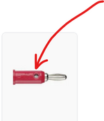
i am outputing the DC voltage into a connector as shown bellow .
What kind of connector do you reccomend i need to plug into my PCB for this purpose?
Thanks.


1692962837029.png


1692962286435.png
 

Attachments

  • 1692962572343.png
    1692962572343.png
    13.4 KB · Views: 53
  • 1692962667435.png
    1692962667435.png
    18.7 KB · Views: 53
Why are you using such low value resistors in the circuit?
You only need 50Ω if you are matching a 50Ω coax cable at high frequencies and banana plugs don't do that.
I put 50 ohms purely because of simulation.

I neet to amplifiy only DC
--- Updated ---

Hello Dana, I have a "microstrip type" board.
the component below has two upper pins two buttom pins and one big pin in the center as shown below.
I only need a connection to the ground a connection to the trace.
How do i locate these 5 pins on my board?
Thanks.

1692970967782.png
 
Last edited:
Pomona datasheet not clear on instructions, but I would venture a guess the 4
connections surrounding the pin connection are no connect, or in your case since
DC only of consideration, just ground them, and the center pin is the electrical
connection of the jack. You should be able to use an ohmmeter to figure this all out,

Or contact Pomona support for help.


Regards, Dana.
 
Hi,
Why are you using such low value resistors in the circuit?
indeed the LT1028 is extremely low noise. If I remember right, then a 50 Ohms resistor noise is about the same as the LT1028 inut noise. Using higher resistor values increases noise.
So regarding noise 50 Ohms is the right choice.
And the current is limited by the feedback resistor of 1600 Ohms. We don´t know supply voltage nor signal voltage.
Total gain is 32 x 32 = 1024 so if the peak output voltage is (guessed) +/-5V, then the first stage output is 160mV and first stage input voltage is about 5mV.
Then the OPAMPs output current is just about 3mA peak.

Mind: The input noise (including resistor) of the first stage OPAMP is amplified by 1024!

I see nothing wrong with the resistor values.

Klaus

Added: I´m familiar with the LT1028, used them in very low noise, high gain applications.
 
Hello Klaus ,The DC voltage of the opamp is +-15V,Yes its a 60dB voltage amplifier.
the input voltage is 1mV.
how do i calculate the noise at the output?
How do i reduce the noise at the output?
I know its a very broad subject if you could give me a direction at least?

I will try and simulation random noise input in LTSPICE to see the output.
what are the main contributors and how to supress noise?

Thanks.
 
Hi,
The DC voltage of the opamp is +-15V
You mean the supply voltage is +/-15V?
If so, and if the input is about 1mV (then the output is about 1V). Then I recommend to lower the supply voltage to decrease the power dissipation and thus decrease the temperature rise.

how do i calculate the noise at the output?
I used: https://www.analog.com/media/en/reference-design-documentation/design-notes/dn015f.pdf

How do i reduce the noise at the output?
* reduce input noise
* reduce bandwith (use low pass filters)
* uses shielded cables and enclosure.
* ensure stable OPAMP condition, EMC proof
* use low noise power supply
* use a proper GND plane
* use film capacitors (if it has a marked pin, then connect it with GND)
* use differential signaling on cables to reduce coupled noise.
* Use low noise resistors, ( MINIMELF usually is better than chip)
* don´t use laser trimmed resistors. (If, then L cut generates less noise then I or II cut)

****
Noise: Very important: what is your signal source, impedance, noise figure?

Klaus
 
Last edited:

LaTeX Commands Quick-Menu:

Part and Inventory Search

Welcome to EDABoard.com

Sponsor

Back
Top