Continue to Site

Welcome to EDAboard.com

Welcome to our site! EDAboard.com is an international Electronics Discussion Forum focused on EDA software, circuits, schematics, books, theory, papers, asic, pld, 8051, DSP, Network, RF, Analog Design, PCB, Service Manuals... and a whole lot more! To participate you need to register. Registration is free. Click here to register now.

AM circuit design - Exercise

Status
Not open for further replies.

IronKeeper

Newbie
Joined
Nov 8, 2021
Messages
1
Helped
0
Reputation
0
Reaction score
0
Trophy points
1
Activity points
17
Hi! I'm solving a college exercise list of a Electronics subject and one of the questions is the exercise 8.10 from the book "Communication Circuits Analysis and Design".

The statement is the following:

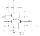
For the circuit below, calculate v0(t) assuming that f(t) is a square wave with transitions between +1 and -1

Can someone please help? I've attached the circuit design.

Thanks!
 

Attachments

  • fig_circuit.PNG
    fig_circuit.PNG
    27.1 KB · Views: 124

The lower NPN turns on to a certain extent, which turns on the upper NPN to a certain extent.

If either bjt remains off, then output voltage would be +10V. Instead your input signals set the 3 transistors fluctuating.

Calculate the resonant frequency of the RLC tank at top. By itself it does not oscillate or resonate. However you're watching to see if harmonic oscillations develop in other sections of the circuit. This could cause resonant action in the RLC tank, and that will cause fluctuations of your output voltage.
 

Status
Not open for further replies.

Similar threads

Part and Inventory Search

Welcome to EDABoard.com

Sponsor

Back
Top