Continue to Site

Welcome to EDAboard.com

Welcome to our site! EDAboard.com is an international Electronics Discussion Forum focused on EDA software, circuits, schematics, books, theory, papers, asic, pld, 8051, DSP, Network, RF, Analog Design, PCB, Service Manuals... and a whole lot more! To participate you need to register. Registration is free. Click here to register now.

Alarm circuit

Status
Not open for further replies.

lucka

Newbie
Joined
May 28, 2022
Messages
2
Helped
0
Reputation
0
Reaction score
0
Trophy points
1
Activity points
26
Hi,

I need to help modify this circuit for battery box 3x 18650 (total is 11.1V)

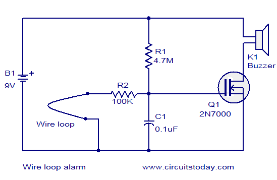
[Original components for 9V]
1x condenser: 0.1 uF
1x resistor: 100K
1x resistor: 4.7M
1x MOSFET: 2N700

my buzzer is at 5-12V I would like to power it 11.1V (box 3x 18650)
can you please advise me which electronic components should i use? (I'm not sure how to calculate it) what components do i need for 11.1V?

I want the batteries to last as long as possible in idle mode.


Thanks.
 

Those components should be fine for 12V operation.

The wire loop I assume fairly short and just a few ohms max resistance ?

One thing to verify, if you have a oscilloscope, is voltage of MOSFET drain
never exceeds 60 volts when buzzer operating. Or goes negative below ground
for any period of time. Reason for this is you do not know exactly what drive circuit
is like inside the buzzer and its electrical noise generation. And MOSFET has a limit
of Vds of 60V.


Regards, Dana.
 
Last edited:

If you look at the FET data sheet here you will see VGS(th) is low >0.8V & <3V.
The 4.7M & 100K resistors form a voltage divider and the resulting gate voltage is not low enough to guarantee the fet will turn fully off.
Changing the 100K to a 10K resistor will solve this problem.

Regards
 

If you look at the FET data sheet here you will see VGS(th) is low >0.8V & <3V.
The 4.7M & 100K resistors form a voltage divider and the resulting gate voltage is not low enough to guarantee the fet will turn fully off.
Changing the 100K to a 10K resistor will solve this problem.

Regards
As I wrote, I was looking at the data sheet but I can't calculate it because I write here :)

So you say exchanging 100k resistance for 10k is better for me?
 

Hi,
If you look at the FET data sheet here you will see VGS(th) is low >0.8V & <3V.
That is misinterpreted

What the datasheet says is:
* If V_GS < 0.8V: I_D is certainly less than 1mA
* If V_GS > 3.0V: I_D is certainly greater than 1mA
(under the given conditions)

Klaus
 

Status
Not open for further replies.

Similar threads

Part and Inventory Search

Welcome to EDABoard.com

Sponsor

Back
Top