igru25
Newbie level 4
Hello,
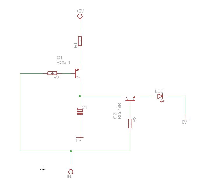
I have made a circuit (strain gauge amplifier) - please see attached circuit.
Non-inverting Schmitt trigger attached to the out of instrumentation amplifier works fine and generates signal (+2V at "high" state, and -1V at "low" state).
So. Theoretically if we attach proper NPN transistor to the out of Schmitt trigger we could control emitter-collector current (36V or 50V capacitor discharge and solenoid action in my case).
It means that capacitor will be discharging as long as we apply pressure on strain gauge and Schmitt trigger in its "high" state.
Till now I don't know how to implement following:
- No pressure applied on strain gauge (capacitor may charge, etc)
- We apply pressure on strain gauge;
- Schmitt trigger switches to its "high" state;
- One short impulse generated and applied to base of our NPN transistor (and no matter how long Schmitt trigger remains in its "high" state).
- To be able to produce next short impulse - Schmitt trigger must be switched to its "low" state before.
On the circuit diagram - our "clever impulse generator" is a red question mark.
Problem Nr. 2: Impulse generator must be adjustable (capacitor discharge control and solenoid action time).
Any ideas are appreciated.
Thanks.