Continue to Site

Welcome to EDAboard.com

Welcome to our site! EDAboard.com is an international Electronics Discussion Forum focused on EDA software, circuits, schematics, books, theory, papers, asic, pld, 8051, DSP, Network, RF, Analog Design, PCB, Service Manuals... and a whole lot more! To participate you need to register. Registration is free. Click here to register now.

adjust lm2576 output voltage with external circuit

Status
Not open for further replies.

firewhale

Junior Member level 1
Joined
Oct 14, 2012
Messages
19
Helped
0
Reputation
0
Reaction score
0
Trophy points
1,281
Activity points
1,398
hi everybody
i am student & decide to design digital switching power supply
i found only tow switching ic in my region lm2576 & l296 that i chose lm2576
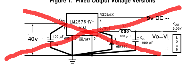
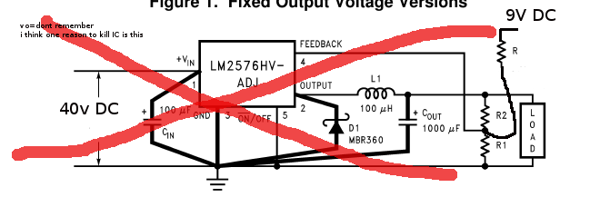
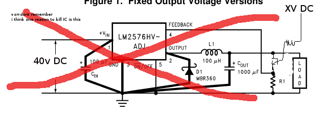
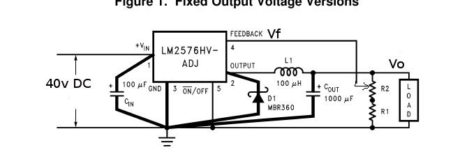
i tired hard to adjust output voltage with external circuit
like use transistor or op-apm or third parallel resistor instead of using a real resistor (R2 in schematic)
In this way the three IC lost their lives 0@)
but not work :(
so pls help me...
 

Do you have a schematic of what you have been trying? You aren't trying to put an external voltage into the feedback pin to adjust it, are you?
 

yes this is first way i tested
direct dc feedback

but not work:cry:
third resistor:

but not work:cry:
one of the reson's may kill regulator this
transistor:

i test this with 2 way
first fed up base with dc
second fed up base with a part of regulator output"Vo"
at tow way i have a bit output change with a couple of base change
in this method Vo≠V(feedbac):|
important:
if i have work with standard method that company Recommended

in any Vo , V(feedback)=1.23
V(feedback) never chaned
I(feedback)=very low=11nA
one thing i can't understand is:
fo=52Khz
in this frequency Xl=32Ω
but xl is very low "its look like fo = 0(inductor resistor is about zero)"
what happend for output???:?:
sorry for bad english:grin:
thanks for replay
i'm waiting...
 
Last edited:

Hi,for inductor under 52KHZ,it's just for store energy,pls don't consider it with filter usage.
For adjust output voltage,the way is to change ratio of R1/R2,but there is one needing to take care:the current go throug R1 must great than certain value.F.Y.I
 

The 1000 uF smoothing capacitor is oversize. During start-up an uncharged capacitor looks like a dead short, with the result that it draws a current surge. I don't know how this affects the lm2576 IC. Seeing your schematic, it appears to carry all current.

I think the smoothing capacitor can be reduced to around 22 uF.

I am running a simulation of a buck converter with coil 100 uH and frequency 52 kHz. It appears to be a workable design.

Screenshot:


I didn't see you state a desired load and volt level, so I'm trying different loads and duty cycles.
For instance, notice that a load of 1A at 19V will result in current peaks of 2A.
If you were to operate it at a faster speed, you could reduce the peaks. It depends on what your coil is designed for.

It would help to get an idea what the controller chip is supposed to do.
If you wish to try the simulation yourself, click the link below. It will open the website where the simulator runs as a Java applet. It will load my schematic, and run it on your computer. (Click Allow to load the Java applet.)

https://tinyurl.com/d987dpo

You can change values by right-clicking on a component and selecting Edit.
 

oh ,really
you right
but
if i change inductor or capacitor Po(Watt) will Reduce in high output, like 2.5A 14V
if i change capacitor to higher than 1mf , output voltage will decrease to 8-9V
otherwise, i test some way to adjust output of lm2576
how can i adjust??
no someone try to Digitize it
how about l296
have somebody tried to Digitize it???
i test the link add here
i have java installed on the system
but site not played. what version of java must be installed (jdk , jre)
sorry for bad english
 

Status
Not open for further replies.

Similar threads

Part and Inventory Search

Welcome to EDABoard.com

Sponsor

Back
Top