Continue to Site

Welcome to EDAboard.com

Welcome to our site! EDAboard.com is an international Electronics Discussion Forum focused on EDA software, circuits, schematics, books, theory, papers, asic, pld, 8051, DSP, Network, RF, Analog Design, PCB, Service Manuals... and a whole lot more! To participate you need to register. Registration is free. Click here to register now.

[SOLVED] ADC0808 giving random values

Status
Not open for further replies.

kaka919

Newbie level 5
Joined
Dec 31, 2015
Messages
10
Helped
0
Reputation
0
Reaction score
0
Trophy points
1
Activity points
96
Adc0808 is giving output 00 for 0v and 255 for 5v which is correct, however for analog input between 0 and 5v, it's giving random values.

Clock to adc is given via timer of 8051. Using timer 0 interrupt, I;m generating a 100 Khz frequency which is given to clock pin of ADC 0808.

Can anyone please help me with this? Thank You


Code:
#define start_conv P3_0
    #define end_conv P3_1
    #define output_enable P3_2
    #define clock_output P3_3
    #define address_latch P3_4
    #define ADDA P3_5
    #define ADDB P3_6
    #define ADDC P3_7
    #define buzzer P0_3
    #define data_bus P1


    unsigned char val=0;
    char buffer[33];


    void mydelay(unsigned int temp)
    {
     while(temp--); 
    } 


    //ISR sequence for the timer 0
    void timer0() interrupt 1
    {
    if(clock_output==1) //conditional statements for the toggle procedure
    clock_output=0;//clock =0
    else
    clock_output=1;//clock = 1
    buzzer=!buzzer;// toggle buzzer just to check
    TF0=0;
    TL0=0XFB;//count for 100 khz which is given as clock to adc
    TH0=0XFF;//count
    TR0=1;
    }
    //ADC conversion function
    unsigned char ADC_conversion()
    {
    unsigned char converted_data=0; //variable to store the A-to-D converted data

     ADDA=0;
     ADDB=0;
     ADDC=0;

 mydelay(2);
 //data_bus=ADC_ch_no;  //sending the address to the Port 1 to select the appropriate channel

 address_latch=1;   //low to high transition to the ALE pin of ADC0808 to latch the address
 mydelay(2);
 start_conv=1;
 mydelay(2);
 address_latch=0;
 start_conv=0;


 while(end_conv==1);
 while(end_conv==0);
 output_enable=1;   //low to high transition on the OE pin to enable the output(to enable extraction of the converted data from the ADC)
 //data_bus=0xFF;   //declaring the Port1 as input port
 mydelay(2);


 converted_data=data_bus;   //storing the data converted into the variable
 output_enable=0;   //reset the OE pin
 //start_conv=0;    //reset the SC pin
 return  converted_data;    //return the converted value
}


void adc_init()
{
     ADDA=0;
     ADDB=0;
     ADDC=0;
     start_conv=0; 
     output_enable=0;
     clock_output=0;
     address_latch=0;
     end_conv=1;

     data_bus=0XFF;

}

void timer_init()
{
    TMOD=0X01;
    TL0=0XFB;
    TH0=0XFF;
    IEN0=0X82;
    TR0=1;
}


//Main function

void main()
{


 buzzer=0;

 lcd_init();
 timer_init();
 adc_init();

 //infinite loop for constant polling the ADC channel for analog values to be captured and converted
 while(1)
 {

  val=(ADC_conversion());   //passing the converted value to port 2
  sprintf(buffer,"%u",val);
  lcd_commandsend(0x06);
  DELAY(5);
  lcd_write(buffer);
  DELAY(5);
  //lcd_commandsend(0x01);

        //and the negation(~) is done considering
        //the LED connections on the controller board
  } //end of the while loop
}   //end of the main function
 

Maybe it's a timing problem and the ADC values are not ready when the reading takes place. Insert a variable delay loop between start and read out to see if this solves the problem.

Enjoy your design work!
 

I used an adc0808 on mc68000 and I first get random numbers when clocked and addressed it with mc68000 out port.
First try all inputs tied together and check the result. If you read good value then address latching not work. If the result garbled then check the clocking.
I get best result with 1MHz TCXO.
 

Adc0808 is giving output 00 for 0v and 255 for 5v which is correct, however for analog input between 0 and 5v, it's giving random values.

Clock to adc is given via timer of 8051. Using timer 0 interrupt, I;m generating a 100 Khz frequency which is given to clock pin of ADC 0808.

Can anyone please help me with this? Thank You

It looks to me that you are confusing CLOCK with START.
CLOCK is a signal sourced by the uC and drives the converter. START is an output from the ADC that signals beginning of conversion, this is the right signal to cause interrupt.
I can't identify the part in your code that produces CLOCK.
 

Code:
void timer0() interrupt 1
    {
    if(clock_output==1) //conditional statements for the toggle procedure
    clock_output=0;//clock =0
    else
    clock_output=1;//clock = 1
    buzzer=!buzzer;// toggle buzzer just to check
    TF0=0;
    TL0=0XFB;//count for 100 khz which is given as clock to adc
    TH0=0XFF;//count
    TR0=1;
    }


This is the part that generates the clock. I have used timer of 8051 to provide clock to ADC0808.
 

What do you mean all inputs tied together?
 

Variable delay loop between start and read out as in? I'm checking the EOC pin to know if the conversion has ended.
I checked in the datasheet that conversion time is 100 microseconds for adc0808. So do you mean enable the start of conversion and wait for approximately the time period required for conversion and then read out the values? I tried implementing that as well, but it's not working. Any other suggestions?
Thank you
 

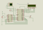
Post your circuit if possible as Proteus file. Also show your full code. If you are testing in Proteus then ADC0808 model has a bug you have to connect D7-D0 of ADC output to D0-D7 (adc input port) of MCU.
 

I have posted the full code above(first post). That is the the first code I tried, eventually modified it numerous times, but still no success. I have neglected the bug regarding adc 0808 model in proteus as of now. adcsimulation.png

Initially I had connected EOC pin to pin 3.1, however it was giving me logic contention error despite proper initialization of eoc pin(refer code). So now after giving start pulse, I'm giving some delay and reading the data but not getting proper output.

Also, on hardware output values of adc displayed on lcd are not changing instantaneously with the change in analog input. It only changes when I switch the off and switch on the power supply of board.

for 0v: 00
for 5v: 255
In between it will give random values.

Note: I'm using P89v51rd2 whose library is not available on proteus.

Advice and suggestions would be highly appreciated.

Thank You
 

use a int type variable to hold the adc result and take 20 adc readings using a loop and then divide the result by 20 to get final result. Maybe this will stabilize the fluctuations.
 

I have posted the full code above(first post). That is the the first code I tried, eventually modified it numerous times, but still no success. I have neglected the bug regarding adc 0808 model in proteus as of now. View attachment 124673

Initially I had connected EOC pin to pin 3.1, however it was giving me logic contention error despite proper initialization of eoc pin(refer code). So now after giving start pulse, I'm giving some delay and reading the data but not getting proper output.

Also, on hardware output values of adc displayed on lcd are not changing instantaneously with the change in analog input. It only changes when I switch the off and switch on the power supply of board.

for 0v: 00
for 5v: 255
In between it will give random values.

Note: I'm using P89v51rd2 whose library is not available on proteus.

Advice and suggestions would be highly appreciated.

Thank You

I cannot see a problem with your code. I think that there could be a problem with the order of port 1. The datasheet is confusing.
My datasheet names pin 17 of the ADC as 2-8(LSB) and pin 21 as 2-1(MSB) , the LSB has to go to P1.0 and MSB to P1.7 which is the opposite order to what you have.
 

I get same problem at first on mc68000+adc0808. When I tied all input together I get the good result of input signal because my addressing rutine was bad.
If tied together the inputs, one of randomly addressed adc get good result. If read it without addressing, get good result. But it is addressing error.

- - - Updated - - -

The ADC0808 is very stable adc. Sensitive for reference voltage. Not need oversampling and dividing for good results.
 

Hi,

Don't let inputs floating.

I recommend to connect unused inputs with a 10k pull down to GND.
Also I recommend to use a small (10nF ?) capacitor very close at each input to GND.

Use a scope to check the input addressing signals.

Some IO pins have multiple functions. Be sure they are setup for GPIO instead of special functions.

Klaus
 

Guys thank you for you suggestion and advice, I finally got the output. Instead of giving clock to adc via timer of 8051, I used a 555 timer IC to generate the clock. And it worked well.
 

Status
Not open for further replies.

Similar threads

Part and Inventory Search

Welcome to EDABoard.com

Sponsor

Back
Top