Continue to Site

Welcome to EDAboard.com

Welcome to our site! EDAboard.com is an international Electronics Discussion Forum focused on EDA software, circuits, schematics, books, theory, papers, asic, pld, 8051, DSP, Network, RF, Analog Design, PCB, Service Manuals... and a whole lot more! To participate you need to register. Registration is free. Click here to register now.

AD9834 DIY signal generator - please verify PCB/schematic

Status
Not open for further replies.

Garyl

Full Member level 5
Joined
Mar 28, 2017
Messages
253
Helped
6
Reputation
12
Reaction score
7
Trophy points
18
Activity points
2,633
Hey,
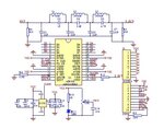
I am going to make a AD9834 signal generator - I will etch the PCB and solder the SMD components, but I like to ask first if the schematic and board is correct.
I have chosen to use the Roland Cordesses PCB project:
**broken link removed**

here is the PCB:
View attachment ad9834N_Cbd.pdf
and the schematic:
View attachment gen9834.pdf

I am going to interface it with Arduino UNO.

and I have followingn questions:
1. Is this PCB and schematic correct?
2. How/where do I buy that U4 20MHz oscillator? There is no part name and searching for 20MHz yields me only common two-pin crystals like the ones used at OSC pins of AVRs and other MCUs
3. For the 20/40/80m receiver/transceiver VFO usage, I need a square waveform output, right?
- The output relay allowing selection of sine/triangle or square waveform can be omitted if not necessary.
4. How do I calculate that low pass filter there for the 20/40/80 bands, and do I have to use separate filter for each band?
- The inductor on the left of the PCB (picture below) is a part of the elliptic low-pass filter rejecting the DDS clock frequency. Such filters can be designed with the help of filter tables in the Zverev's "Handbook of Filter Synthesis" (or in the much less expensive "ARRL Handbook") or with one of the many softwares available.
I have seen such calculators, but how do I choose frequency limits, etc?
**broken link removed**
I'd like to get a wide band covered in my receiver.
5. Do you have any other suggestions/hints for me using that DDS project for my ham receiver?
Thanks in advance!
 

Buddy..
I admire your courage but you try to realize a complex project that exceeds your level.
1-Such PCBs should have double layer due to high GND noises.That disturbs everywhere including itself.
2-www.digikey.com ( or at some others like mouser,arrow but look at www.octopart.com to get more information and just search what you want)and pay attention the specifications !!Some IC circuits need some special characteristics.
3-VFO should be a sine-wave to my knowledge.(not sure)
4-BandPass Filters for Amateur Bands have high out-of-band rejection and attenuation levels.RC filters cannot be used there.In order to get a reasonable result, crystal filters are best if they are available.
Those Filters can be connected in parallel with SPnT RF Switches or they can be inserted to the circuit mechanically ( jumper,a good high quality commutator etc.).Elliptic Filters can also be used and they are L-C filters at that frequency.More information, see. Filter Design Softwares.
 

I admire your courage but you try to realize a complex project that exceeds your level.
1-Such PCBs should have double layer due to high GND noises.That disturbs everywhere including itself.
I realize that it needs to be double layer and I will etch that. I just do the iron transfer method on one side and completly cover the second side and it works, it already worked in the past.
Is there anything else problematic I need to know?


2-www.digikey.com ( or at some others like mouser,arrow but look at www.octopart.com to get more information and just search what you want)and pay attention the specifications !!Some IC circuits need some special characteristics.
I have tried to look in the shop I usually buy stuff but they charge over 11$ for a single crystal of that type:
osciii.png
Suprisingly, the entire DDS module (altough a bit lower max frequency, over 10MHz if I remember correctly) costs around 5$ there:
ddsSelling.png

3-VFO should be a sine-wave to my knowledge.(not sure)
Well, the same I saw on the oscillscope when I was probing theVFOs

4-BandPass Filters for Amateur Bands have high out-of-band rejection and attenuation levels.RC filters cannot be used there.In order to get a reasonable result, crystal filters are best if they are available.
Those Filters can be connected in parallel with SPnT RF Switches or they can be inserted to the circuit mechanically ( jumper,a good high quality commutator etc.).Elliptic Filters can also be used and they are L-C filters at that frequency.More information, see. Filter Design Softwares.
My friend gave me such schematic and said that Ican try just adjusting the component values for the filter showned here above the chips:
AD9850brd.jpg
but right I nnow I have no idea how toadjust them.
By Filter Design Software, do you mean PC applications like https://www.nuhertz.com/ ?
Or maybe that: https://www.microchip.com/development-tools/resources/filterlab-filter-design-software
FilterLab® 2.0 is an innovative software tool that simplifies active filter design. Available at no cost from Microchip’s web site (www.microchip.com), the FilterLab® 2.0 active filter software design tool provides full schematic diagrams of the filter circuit with recommended component values and displays the frequency response.


Status
Not open for further replies.

Part and Inventory Search

Welcome to EDABoard.com

Sponsor

Back
Top