CQCQ
Member level 3
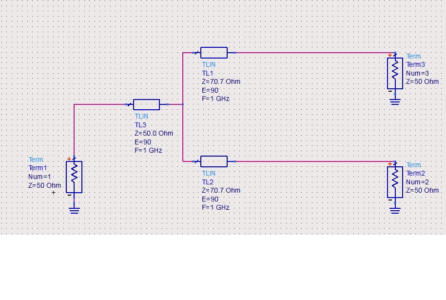
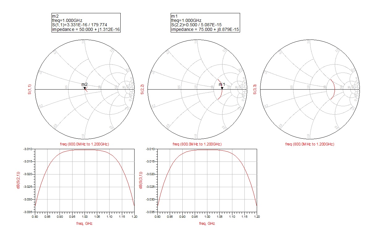
Hi!I got a simple but awkward problem about the T-juntion power divider.I am using a T-juntion power divider to dividing a signal from port1(50ohm) to port2 and port3 and the two port's are 25ohm load(pic1).While from the simulating result(pic2) I see the port1 is matched to 50ohm ,but the port2,3's impedence are 75ohm not matched to 25ohm.So I have some questions....
1.I see the port 1 is matched to 50ohm but port2,3 are not matched.So I think it's have refelction loss in the circuit but why the IL is also ideal 3 dB?
2.What is the real impedence of port2,3? I'm using two-section 1/4 line to transform the 25ohm to 50ohm I think that is right way ,but why the port2,3's impedence are 75ohm not 25ohm?