Continue to Site

Welcome to EDAboard.com

Welcome to our site! EDAboard.com is an international Electronics Discussion Forum focused on EDA software, circuits, schematics, books, theory, papers, asic, pld, 8051, DSP, Network, RF, Analog Design, PCB, Service Manuals... and a whole lot more! To participate you need to register. Registration is free. Click here to register now.

About current mode buck converter

Status
Not open for further replies.

arsenal

Full Member level 2
Joined
Oct 17, 2004
Messages
143
Helped
15
Reputation
30
Reaction score
4
Trophy points
1,298
Activity points
1,103
hi,

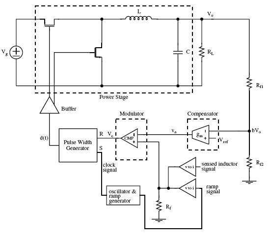
Im new on buck design. Just wonder, for current mode buck shown in the attached pic, how to decide the value of Rf? And if I use current comparator instead of the voltage comparator as the modulator, then I don't have to use Rf, is that correct? Then, which is better? current-comparator as the modulator, or voltage-comparator with Rf?

thanks
arsenal


Rf's are the sampling circuit. You can't change the voltage comparator because you must compare the voltage sample of Vo to the voltage of Vref.

If Vo =12V desired value and Vref = 2.4V
then (Vo*rf2)/(Rf1+rf2) must be 2.4V
 

Hello arsenal,
You will still need to use Rf or you will not have a controlled output voltage. Rf1/Rf2 is just a potential divider feeding into a voltage comparator that generates a voltage potential equal to Vref when the output voltage is equal to the wanted voltage, the internal modulator circuit then switches off the pass transistor for a short period. See the ICs datasheet for the details of these values. The current through the divider can be any convenient low value. The current feedback loop is normally implemented in addition to the voltage feedback loop to limit the current to a safe value under load limit or fault conditions.

You have not said what your chosen device is so it is difficult to give specific recommendations, looking at the datasheet and referring to the app notes that are on most PSU IC manufactures websites should give you all the info you need.

Inductor design is quite critical for a Buck regulator but there are lots of references on the Internet, usually on manufacturers websites such as EPCOS, Feroxcube, Magnetics Inc. etc. on how to do this, some of them even have quite good design software that you can download too.

Best regards
Bob.
 

thanks Miguel ,

But u are talking about the comparator which compares feedback voltage and reference voltage. I was refering to the one labeled as Modulator in the picture, and how about this Rf before the modulator?

thanks

Miguel Gaspar said:
Rf's are the sampling circuit. You can't change the voltage comparator because you must compare the voltage sample of Vo to the voltage of Vref.

If Vo =12V desired value and Vref = 2.4V
then (Vo*rf2)/(Rf1+rf2) must be 2.4V

Added after 3 minutes:

thanks bob,
I am talking about Rf at the output of the 2 voltage-to-current converters. Sorry I didn't make it clear.

thanks
 

Status
Not open for further replies.

Part and Inventory Search

Welcome to EDABoard.com

Sponsor

Back
Top