Continue to Site

Welcome to EDAboard.com

Welcome to our site! EDAboard.com is an international Electronics Discussion Forum focused on EDA software, circuits, schematics, books, theory, papers, asic, pld, 8051, DSP, Network, RF, Analog Design, PCB, Service Manuals... and a whole lot more! To participate you need to register. Registration is free. Click here to register now.

About connection of the Filter and VCO in PLL design

Status
Not open for further replies.
gaom9 said:


Hi, saro_k_82

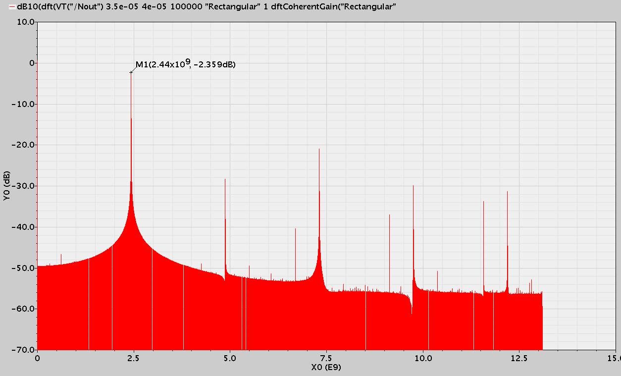
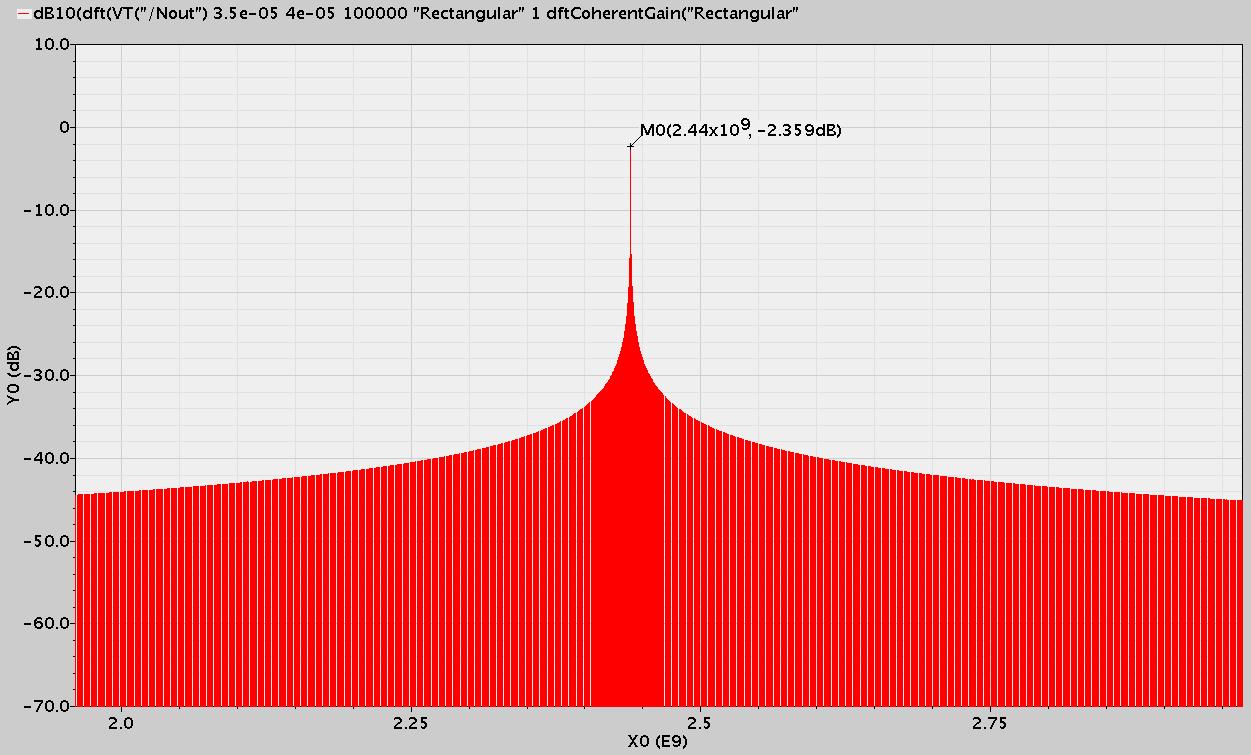
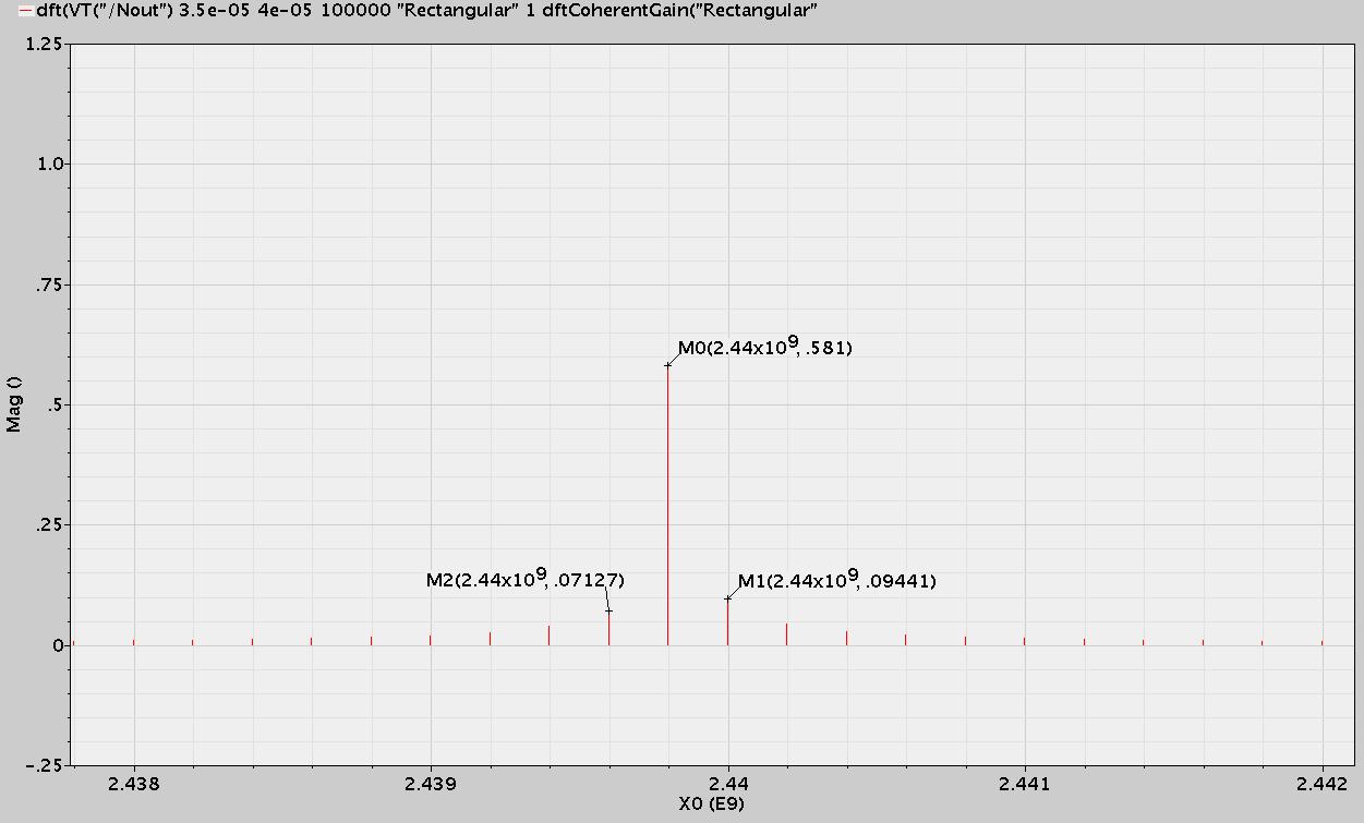
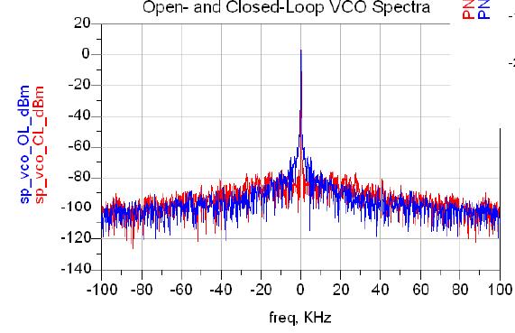
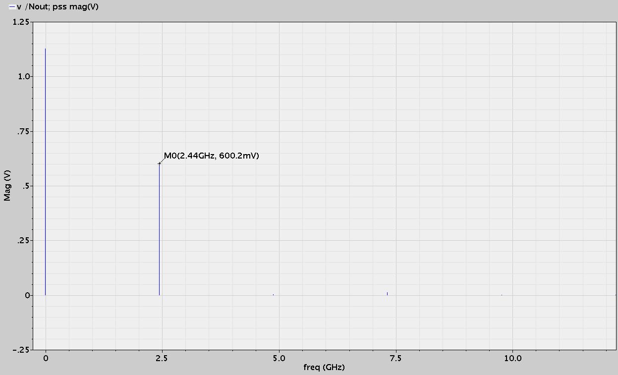
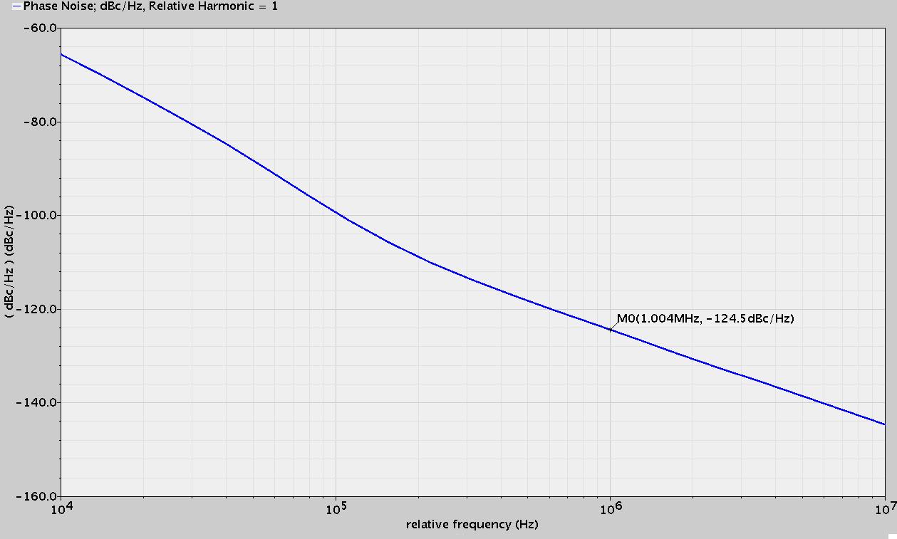
The PSS frequency spectrum and Phase noise figure is shown above.
There is no tones at 500K, so it was generated by tran sim.
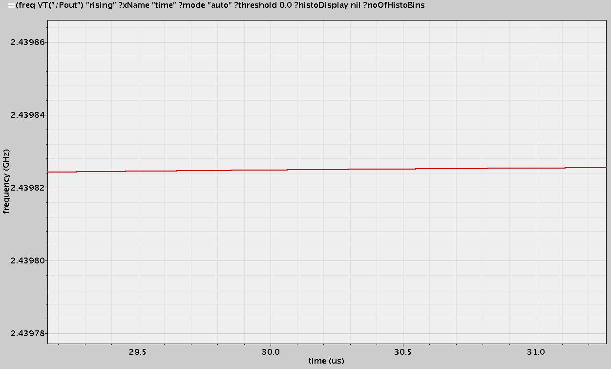
And the phase noise is -124.5dBc/Hz at 1MHz offset, I think it is enough for my use.

My problem has been solved.

Thank you, everyone.
Best regards!


Hi, I can't see figures could you please upload again ?
 

Hi, I am sorry to reply quite late. It took a lot time to run a 40us tran simulation with the 2.4GHz VCO.
I set a tighter tolerances, reltol 1e-5, vabsto 3e-8 iabstol 1e-13 Method gear2only and errpreset=conservative. The psd result is shown below. And the Y axis is in dB10 unit

Fig 1 the psd in whole frequency


Fig 2 the psd in near 2.44G frequency


Fig 3 the psd result in mag unit


Fig 4 the output frequency from the "freq" function has been stable in this simulation.


What about this psd result? Is it OK?

And when in the total Δ-Σ Fractional-N Frequency Synthesizers simulation, what's the value of the spur of the output signal should be to ensure a clean signal. I find some paper shows that the spur of the output signal is about -80dBc...it is quite large, and here the VCO output psd shows that the spur is more than -40dBc, I am worried that the system can not achieve this performance...
What is the relationship of the VCO psd result and the frequency synthesizers output psd?

Hi, AdvaRes
Thank you for your reply. But I think the pic is all right, I can see them normally.

Thank you!
Best regards!
 

Hi,
I am running the total simulation of the Frequency Synthesizers with the Analog circuit in transistor level.
I set a tighter tolerances, reltol 1e-5, vabsto 3e-8 iabstol 1e-13 Method gear2only and errpreset=conservative. I find it cost a quite long time to do so, I want to do a 100uS tran simulaiton, but after 12 hours, it only simulation to 1.3us, so it will cost about 50days to finish it...
Is there any method to reduce the simulation time, please?

Thank you!
Best regards!
 

gaom9 said:
Hi,
I am running the total simulation of the Frequency Synthesizers with the Analog circuit in transistor level.
I set a tighter tolerances, reltol 1e-5, vabsto 3e-8 iabstol 1e-13 Method gear2only and errpreset=conservative. I find it cost a quite long time to do so, I want to do a 100uS tran simulaiton, but after 12 hours, it only simulation to 1.3us, so it will cost about 50days to finish it...
Is there any method to reduce the simulation time, please?

Thank you!
Best regards!

Unfortunately there is no solution. I'm facing the same problem.
:idea:
If you afford, buy a powerfull workstation (octa or quad-cores with a huge RAM).
 

Hi, I use the quad-cores workstation, but is the spectre tran simulation a single thread process, Can it run in multi threads to save the simulation time? And how to run it, please?

Thank you.
Best regards!
 

You need to find out the source of that 500KHz noise. When everything except the VCO is ideal, you shouldn't see any noise spur.
The spur specs are for the spurs from the sig-delta block when the loop is closed. The bargains are different and at this stage there is nothing that tells you that those specs are unachievable.
"What is the relationship of the VCO psd result and the frequency synthesizers output psd? "
You can get this from any book or tutorial that covers the basics of PLL.

The tolerances are way too unforgiving now. Try with reltol 1e-4,vabstol 1e-6, iabstol 1e-12 and conservative. why are you running it for 100us?
 

    gaom9

    Points: 2
    Helpful Answer Positive Rating
In the last simulation with moderate mode, the Frequency Synthesizers will settle in about 20us, so I want to run a long time to check is it working stable.

And in my reply above, the 500k dither means that when I use the moderate mode to run the tran simulation, the output frequency is change within 500KHz at the center frequncy of 2.44G which shown in the 'freq' function result, but not means a 500KHz noise, when I change the mode to conservative, the output frequency is much stabler.

And I find the spectrum of the dsf result is different from the figure below, the Y axis unit of the following figure is dBm, how can I get the same figure in cadence? I want to know what is the performance of the VCO? Because the spectrum of many papers are as the format as the following figure, so I want to make a comparation with them.


And I will change the simulation mode and run it again, thank you.

Best regards!
 

VCO's are low Q (about 10) and so dont take 20us to settle., the entire PLL lock time would be like 2 to 20us which is dominated by the loop BW. VCO will settle in Q cycles to within 1%.
The spurs seen on the dft plot are due to finite sampling frequency --> aliasing and spectral leakage. Need not worry about that. If you adjust your window size so that it accomodates integer multiples of the carrier, the spurs will reduce a lot.
Phase noise is always expressed in dBc/Hz., but it you want to see it on any other axis, you can go to the result browser and plot the pnoise result from there.
 

Thank you, saro_k_82.
I will try it.

And here is a paper about the dft in cadence, may it helpful to people here.
 

I have same problem as this one, how did you manage to make your differential output symmetrical? Did you only tweak the transistor size? Does the cuurent is still 40nA at different tuning range?
 

Helle goam9:

~1kohm resistor before Vtune as you mentioned is common practice.
Just check it out with behavior simulation if doubt the loop response.
 

good discussion for VCO output balance, thank you~~
 

Status
Not open for further replies.

Part and Inventory Search

Welcome to EDABoard.com

Sponsor

Back
Top