Continue to Site

Welcome to EDAboard.com

Welcome to our site! EDAboard.com is an international Electronics Discussion Forum focused on EDA software, circuits, schematics, books, theory, papers, asic, pld, 8051, DSP, Network, RF, Analog Design, PCB, Service Manuals... and a whole lot more! To participate you need to register. Registration is free. Click here to register now.

About 3 Phase IGBT pack

Status
Not open for further replies.

mutlu_sgul

Junior Member level 1
Joined
Mar 13, 2007
Messages
16
Helped
1
Reputation
2
Reaction score
0
Trophy points
1,281
Activity points
1,411
igbt pack

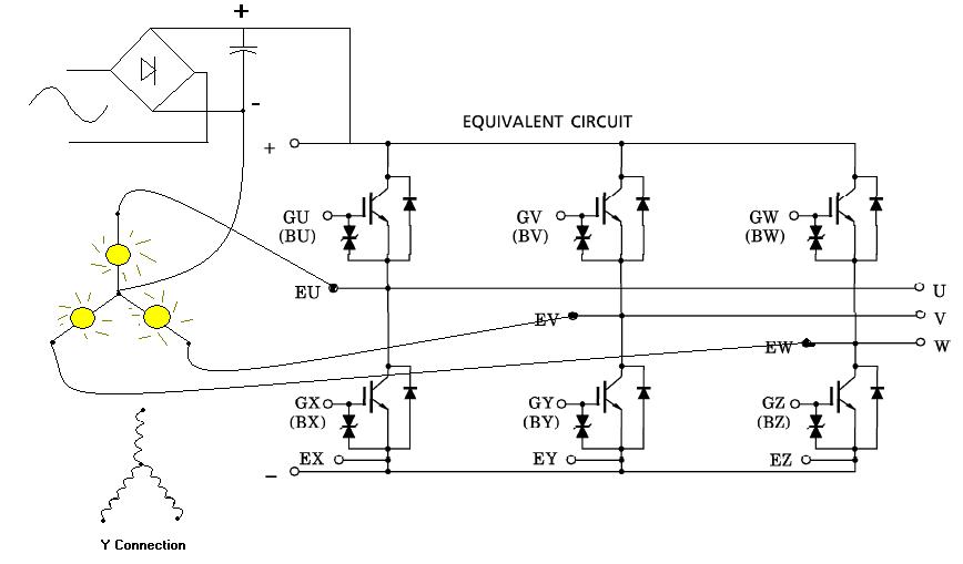
Hello Friends. I have a problem about IGBT switchig. I have connected a full wave rectifier to the Ac line and convert it to the DC 220V. Also I connect a Capacitor to rgulate the Dc voltage. Then I connect this voltage to the MG15Q6ES42 IGBT module. then also I connected Y connected three lamps as a induciton motor. (Simulate it) I apply DC 20 V to the gate terminals but I could not switch the IGBT module and see the lamps lights. I am tring to construct three phase induction motor drive. If any one could help me I will be so thankfull... Thanks...
 

how to connect 3 phase motor u v w

Hopefully you have a data sheet? There are 6 gate inputs, so which did you try setting to on? By the way, must not power the module with open gate circuits, you should at least connect a resistor or a short to set unconnected IGBT to off and to avoid damage by ESD.
 

3 phase igbt testing

I hope you have connected your lamps in this way.


Please add resistor when applying the 20V to the gate, I think you'r applying the maximum 20V to the gate terminal, as I have seen in the datasheet with the name of GATE-EMITTER Voltage.Don't apply 20V instead drop it to around 15V or something less, use resistor.I can't find the gate current, so I don't know which resistor value to use.More importantly from where your are applying 20V to the gate terminal with respect to what?.Even if you apply the 120V to the gate, it wouldn't work this way, unless you connect it's ground properly.You have to connect the 20V input ground to the ground of the Y connected lamp ground for properly turning ON the transistor.Use around 10K resistance or something like that, apply 20V if this didn't work,try using lesser resistance value, but go down gradually, like 8.7 or something like that.If a resistance one end is connected to GATE and other end connected to 20V.So it would be safe, you would be getting lower Voltage at the GATE terminal.

Slightly off the topic,I would recommend you to switch down from 220V to 12V and instead of using the lamps, buy inexpensive 12V torch bulbs and do the experiments to carry out the test.It would be much safer and there is less likelihood of damaging the components.Even if you short the secondary of transformer(220V-12V of 500mA-1A) for more than 15 minute, nothing would happen,I have made this mistake once, transformer got very hot after 15min,but didn't broke down.If I would be carrying out the experiment at 220V, there would be any mercy!.I don't know how much time could it carry on in this way.Once you are confident about the proper working of the circuit, just switch it to high voltages.
 

igbt 220vac 3 phase

the above picture is rediculos. If you connect gnd to common in the star connection it has no reason to use six igbts because you can connect only 3 to have the same result . The important thing is that controll voltage which is in turn of 15 VDC MUST be isolated for each upper leg of the bridge. Lower leg of the bridge can have common ground for all 3 controll voltages but they must be isolated from upper legs. The resistance in the gate can range from 10 - 100 R.
Greetings
Dragan
 

three phase capacitor pack

The good thing with the Toshiba IGBT Sixpack is, that they have supressor diodes at the gates to protect against ESD. That's not a common feature of IGBT or IGBT modules. Uge of 20 V is actually maximum rating, 12 to 15v would be normal. For a resistor, even with 600A IGBT, 10k is o. k. It isn't more than a protection in case of gate open circuit.

Your test circuit has the advantage of allowing a test of single IGBT and no danger of short circuit, I guessed our colleague would have supplied DC link terminals (as in normal operation), thus also raising the question of possible bridge shorts.

I wonder, what this kind of test could show, except from IGBT actually acting as switch. Would be different with driver circuits fully assembled, then you should be sure, that correct gate voltage is applied and no bridge shorts are brought on.
 

3 phase igbt

dragan wrote:
the above picture is rediculos. If you connect gnd to common in the star connection it has no reason to use six igbts because you can connect only 3 to have the same result.

Because, mutlu_sgul was only controlling the three lamps and thus only 3 IGBTs are required not six of them.It just a module with 6 built in IGBTs, it depends on you as how much you want to you use.I think in this case for simulating the inductor motor replaced with lamps, only 3 IGBTs are required.

mutlu_sgul wrote:
I have connected a full wave rectifier to the Ac line and convert it to the DC 220V. Also I connect a Capacitor to rgulate the Dc voltage. Then I connect this voltage to the MG15Q6ES42 IGBT module. then also I connected Y connected three lamps as a induciton motor.

FvM wrote:
I wonder, what this kind of test could show, except from IGBT actually acting as switch. Would be different with driver circuits fully assembled, then you should be sure, that correct gate voltage is applied and no bridge shorts are brought on.

Yes, they are acting as a switch and I think IGBTs would be used in switch mode in this application, turning ON/OFF very fastly, working in a PWM fashion for providing the wide range of average values across its collector-emitter voltage.
 

theory igbt switches 3 phase

I said that I have connected a 220V rms rectifier and I got a 340 V of a Dc voltage. This voltage may damage my lamps If I connect my 220V lamps in delta so I connect these lamps in Y configuration. I didn't connect the center of the Y to the - of the capacitor. I just connect the terminals of the Y connected lamps to the Toshiba U V W terminals.

Also I connect 10KOhm resistors to the BU BV BW and BX BY BZ terminals of the IGBT pack then I connect the other terminals of these resistors to the - terminal of the capacitor. So all resistors connected to the same ground. I think the main problem is here.

Then I open my DC power supply and connect - terminal of it to the - terminal of the capacitor. And adjust it to 19V Dc. I connect two resistors of 10 Ohm to the + terminal of my power supply. I will use the other erminals of these resistors to gate my IGBTs. I connect these two resistors for example to BX and BV. But I have never ever see the lamps light.

When I connect a single lamp to the one of IGBT's collector and the other terminal of the lamp to the + terminal of the capacitor and when I connect emiter of this IGBt to the - terminal of the capacitor finally when I apply 15 volt DC voltage in a same way I saw the lamps light.

I know the short circuit risk of the bridge so I have never ever try to gates BX and BU or BY and BV or BZ and BW.

It's good idea to connect 3 IGBTs but I design this circuit to drive delta connected motor and I think I should connect six IGBTs to do that. The reason of connecting the lamps in Y just to prevent damage of the lamps.

If you have any circuit diagrams that demonstate how should I connect all the circut I will be hopefull... Or how I isolate the gate voltages.

Thanks...
 

The intention of simulating the motor was stated at the beginning of the discusion.It means that all that i stated aplies to simulated circuit. If you want to switch just 3 lamps you can do this by using lower igbts and connect their emiters to common ground. In this case you do not need to take care of short circuit and the piloting part of the circuit need not to be isolated phase to phase. BUT in the real world if you want to controll 6pack bridge you must controll upper legs of the igbt from isolated controll voltage or you can use the bootstrap circuit. Using 10K resistor in the gate will only heat your igbt because instead of having normal slope of 4-10 uS in igbt openning you will have the linear part of the operation which is much longer ( i will not explain the miller zone here ) and this will increase the heating of the IGBT.
Greetings
Dragan
 

Thanks at all. Now I manage to switch the IGBT bridge. I used 6 isolated 15 V power supplies to switch 6 channel IGBT pack. Thanks
 

How you did that? I have made the configuration in the above picture, did you do that in the same manner?if not then please tell me briefly, so I also can learn.
 

Status
Not open for further replies.

Similar threads

Part and Inventory Search

Welcome to EDABoard.com

Sponsor

Back
Top