Continue to Site

Welcome to EDAboard.com

Welcome to our site! EDAboard.com is an international Electronics Discussion Forum focused on EDA software, circuits, schematics, books, theory, papers, asic, pld, 8051, DSP, Network, RF, Analog Design, PCB, Service Manuals... and a whole lot more! To participate you need to register. Registration is free. Click here to register now.

A non tesla method of electrical energy tramsmission

Status
Not open for further replies.
tesla was supposed to have developed a way to broadcast power

since you tried this at home, what did you actually use?
lets call the device described in your first posts a device
lets call whatever used the transmitted energy a machine

how much power went into your device and how much power was used by the machine?
 

--- Updated ---


I have tried it at home.I do not need anybody’s advice.

So, then why do you come here for? To troll?
I believe that I've seen you, or someone identical to you, in other forums, making similar outlandish claims and then quarreling with people who attempt to reason with you.

Poor Nikola Tesla. If only he had known, how much people would use his name to make preposterous claims.
 

Electrified railways systems,the rail resistance transmission/ electrical energy loss is high.With single wire transmission ,it is totally eliminated.
The wheel carriage of rail road coach will need iron wheels only for
Traction guidance.The coaches could have tyred wheel like the eighteen wheelers and be totally noiseless and vibrationless.
 

sorry, i don't think your system will provide enough energy to run trains
you haven't shown any results of the test you made
you haven't shown how your transmission system is rec

since you tried it at home, please show some results
what did you build, what you measure, adn what did you get?
 

No, not others have to proove it.
It's your job to proove it when you start such a thread.

Klaus
 

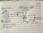
Mosquito killing racket is my 4000 volts generstor,loudspeaker voice coil is my delay line plus audio sensor,aluminium folded foils as electroscope indicators....opening and closing with the screw driver blade shorting 4000 volts to zero volts during tests.
 

Attachments

  • 70C271B9-DE5C-4EDF-9048-4CF4DE16C812.jpeg
    70C271B9-DE5C-4EDF-9048-4CF4DE16C812.jpeg
    518.8 KB · Views: 285

As previously mentioned, the test setup "works" (speaker click, spectrometer action) because the voltage source isn't actually floating. We don't know the exact construction of the mosquito rack, but the 0V terminal is most likely grounded through the power supply. If not, the case ground capacitance is sufficient to deliver charge to the connected circuit. Also the electrometer is indicating voltage referred to ground. Although the circuit may seem floating to an uneducated observer, it actually isn't.
 

Maybe some reference to Oliver Hevisides work would help you on this.... Plus maybe Thevorin.
Current will not flow without a return path...
 

Status
Not open for further replies.

Part and Inventory Search

Welcome to EDABoard.com

Sponsor

Back
Top