Vermes
Advanced Member level 4
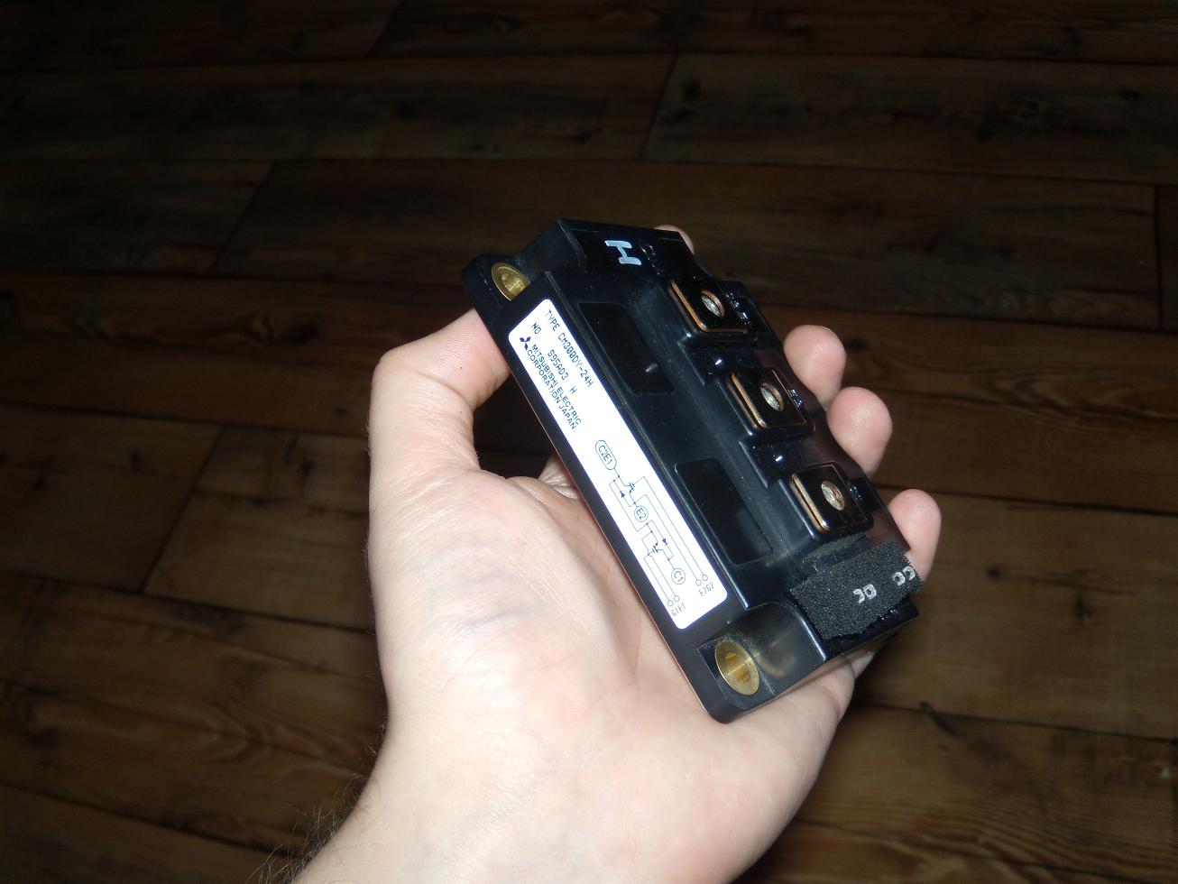
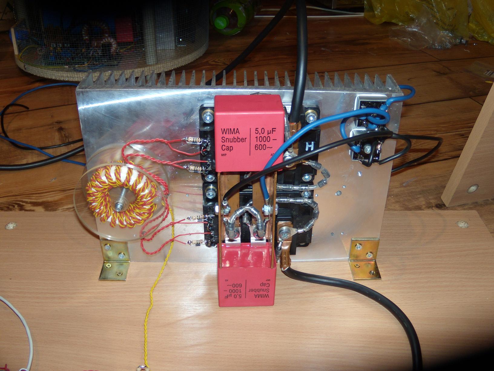
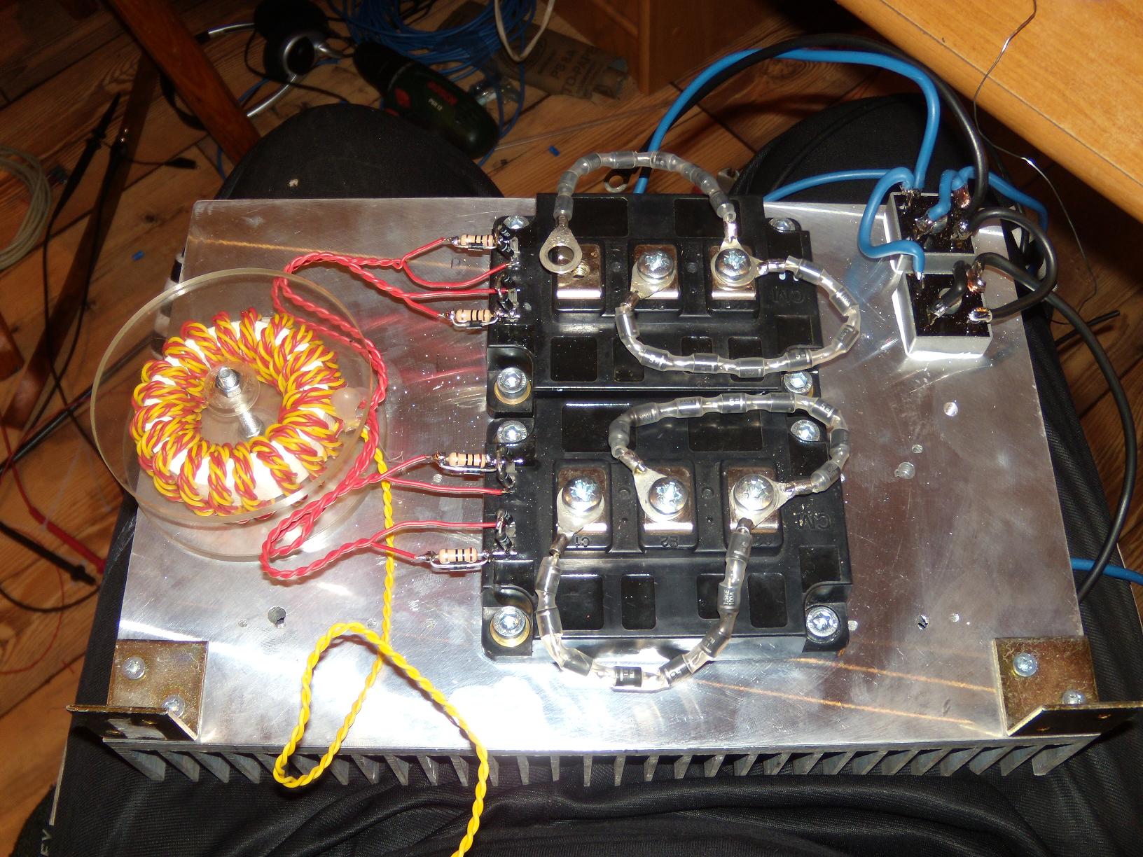
Transistors used in this device are IGBT, product of Mitsubishi Electronic – CM300DY24HA. Their parameters: maximum continuous current – 300 A, maximum tension C-E – 1200V. It is available to make them work in resonance in frequencies of 60kHz and more. Tests by American Tesla workers in the USA showed, that the transistors can last pulses to 4kA without any damage to them in this application. At 5kA they explode as a result of being out of density. They can be easily used with the pulse currents to 2kA.
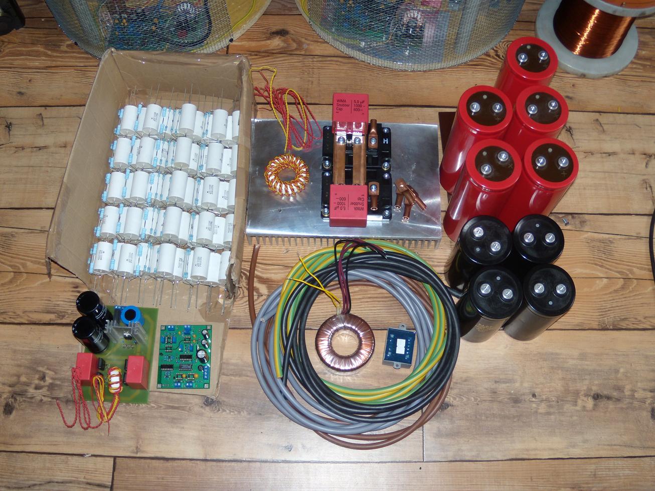
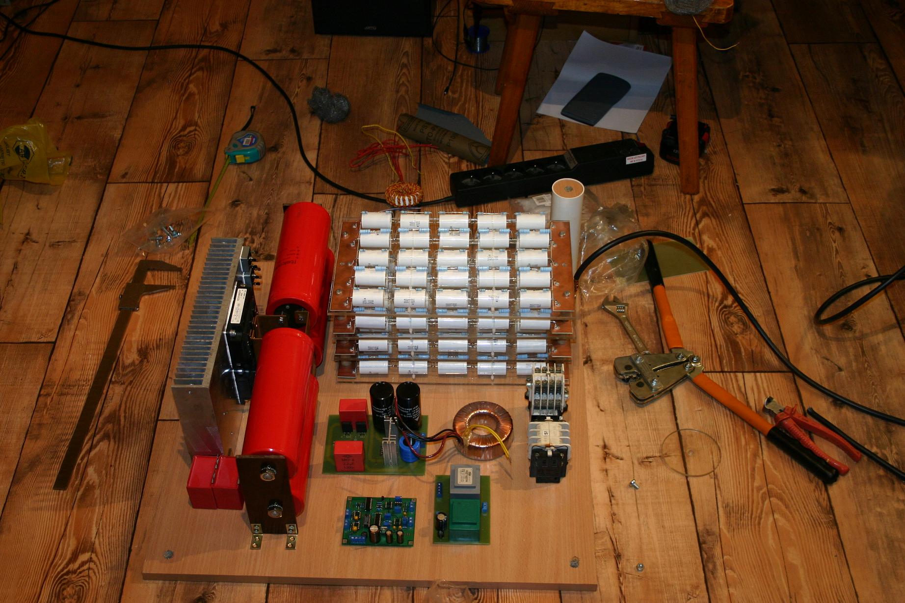
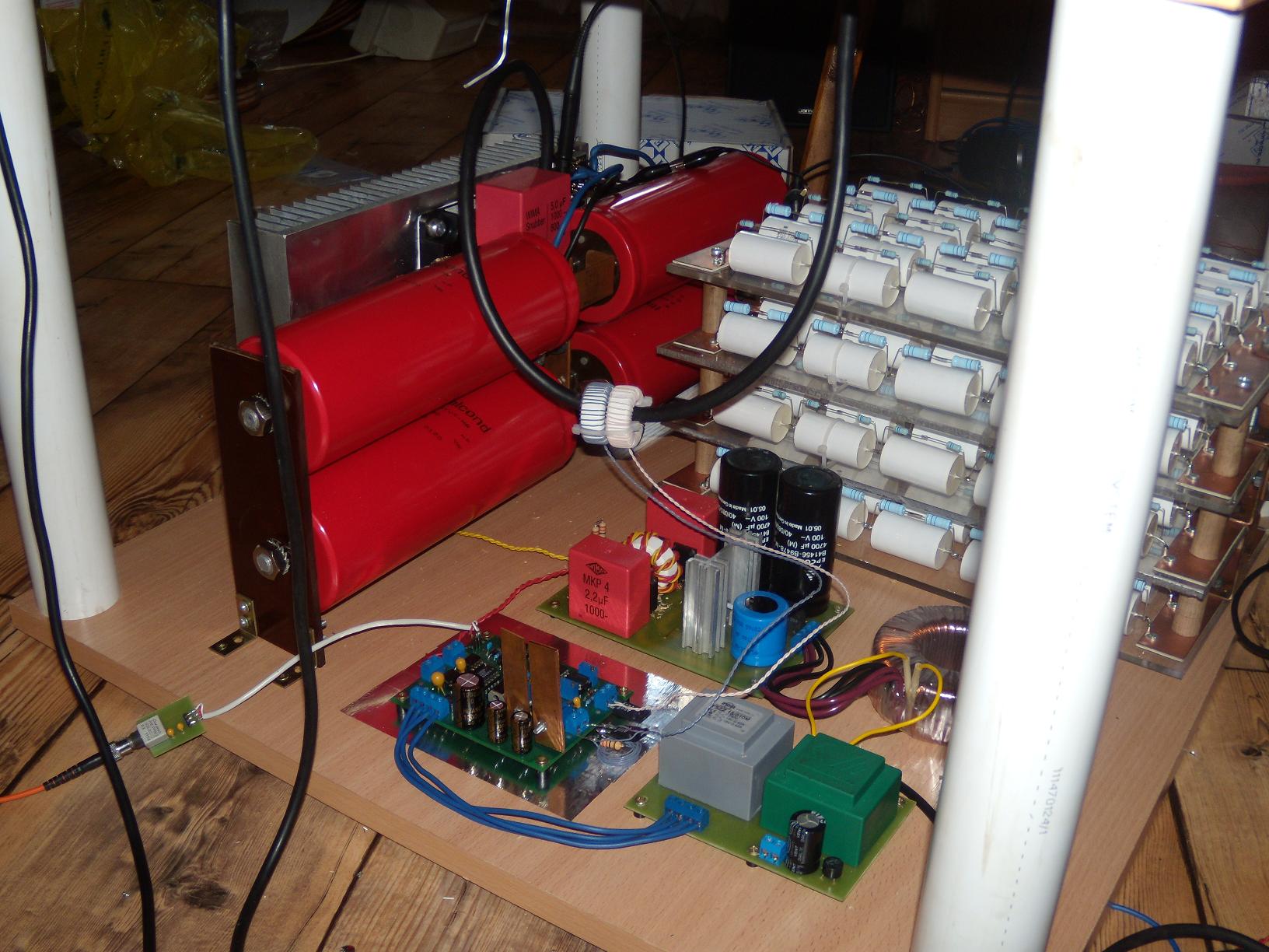
The transistors are secured by TVS which can dissipate about 12kW and snubbers 5uF/1kV in the supply.
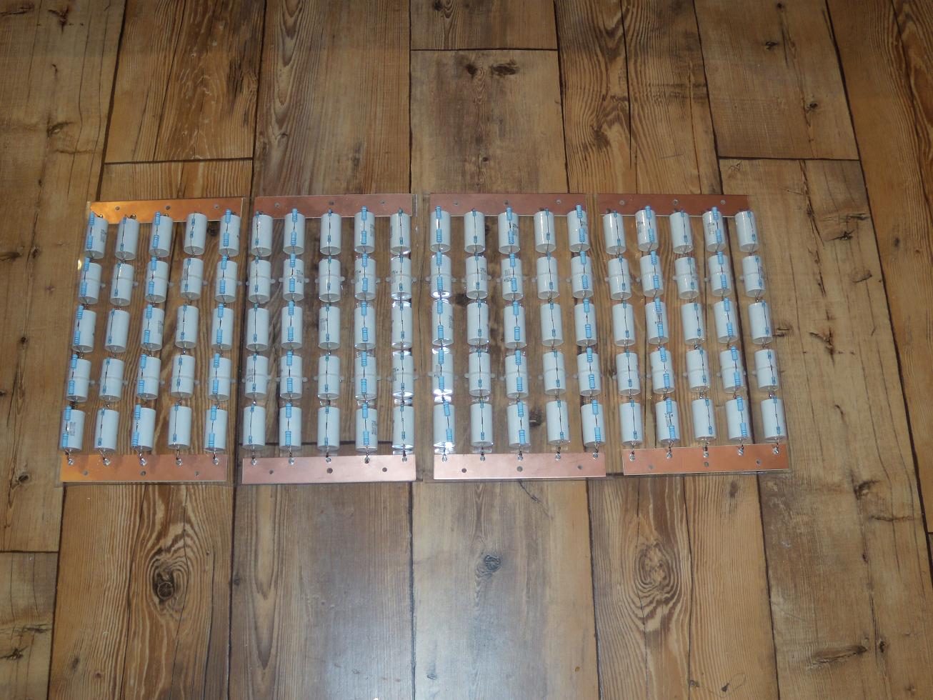
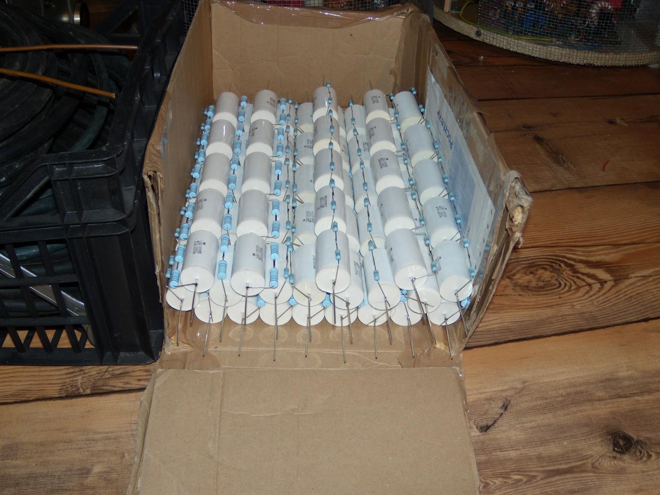
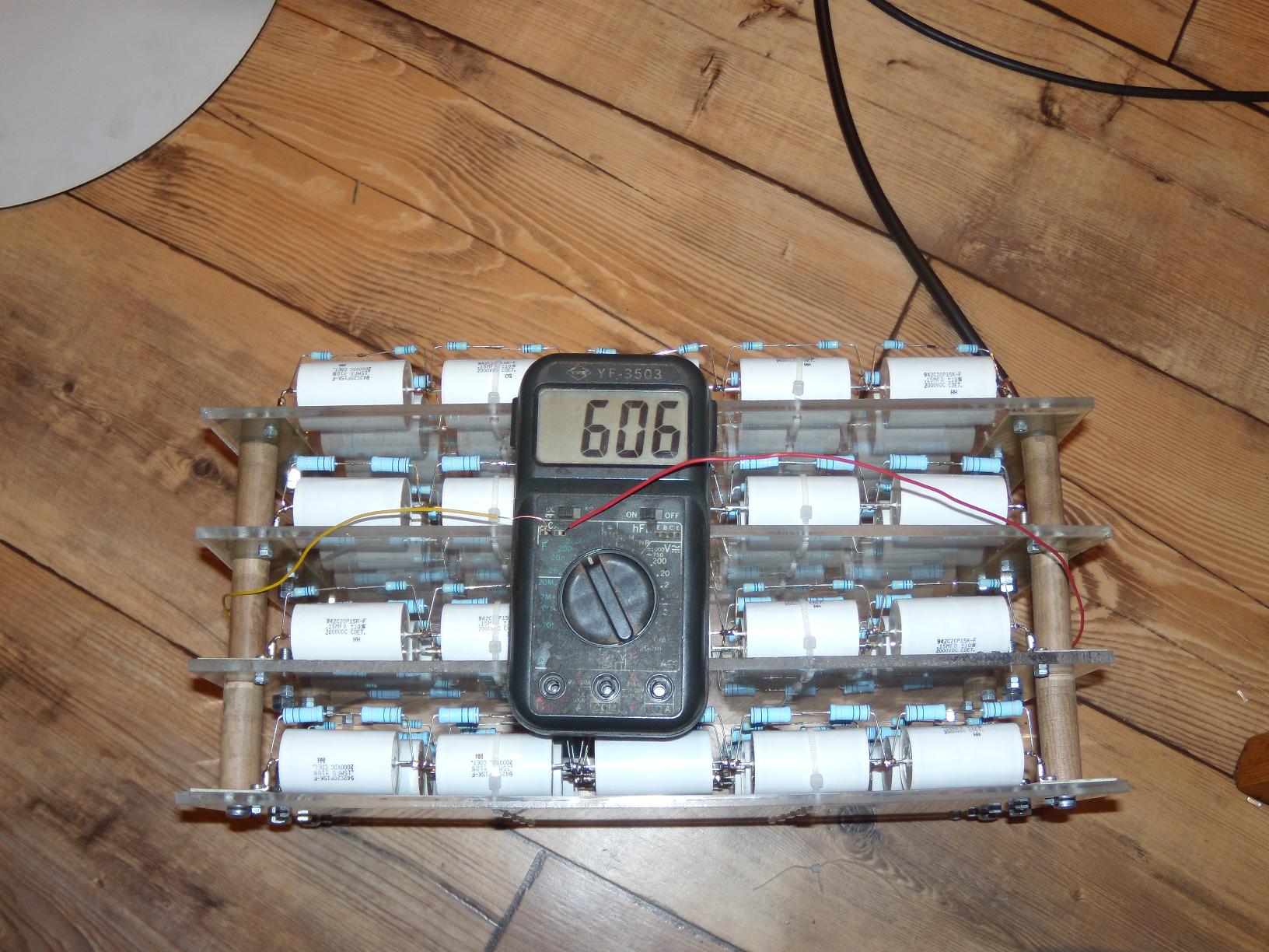
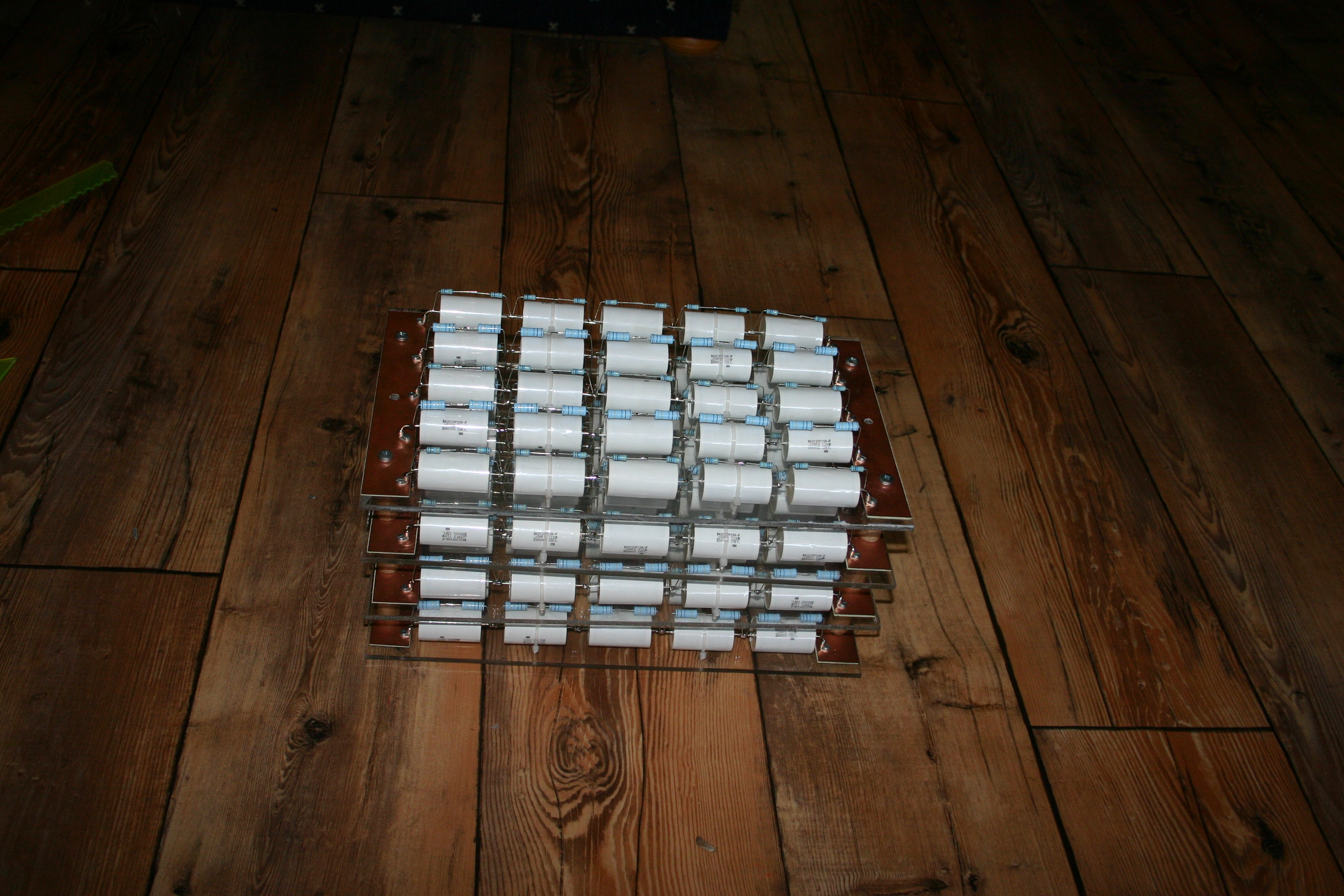
Any of DRSSTC cannot work without a resonance capacitor. The bigger capacity it has, the better it is and also, unfortunately, more expensive.
Another important thing is the breakdown voltage, minimum is about 8kV.
Finally, the parameters are 600nF/10kV, what means that a hundred of CDE942C20P15kF capacitors are needed.
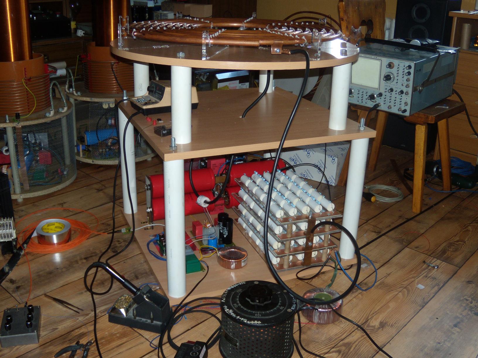
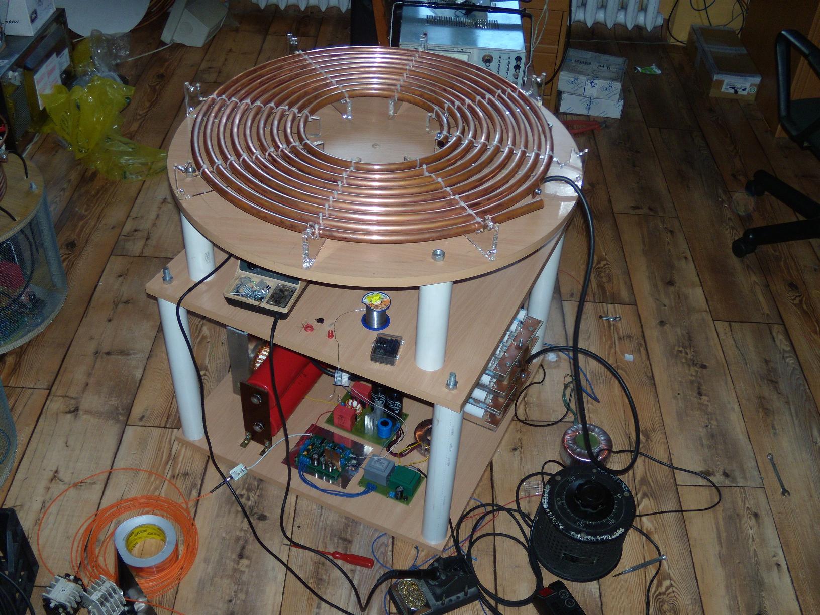
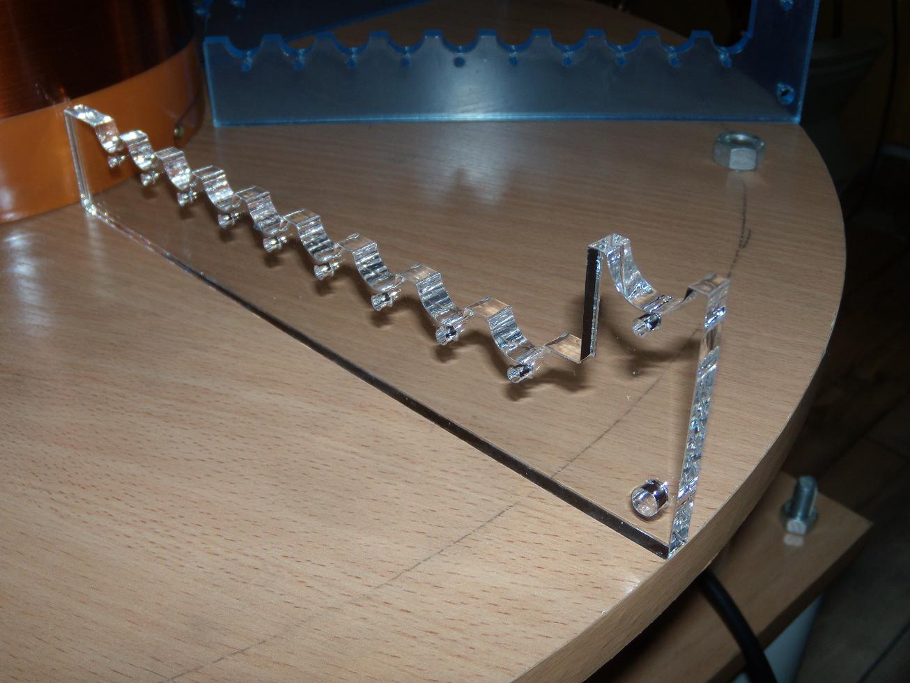
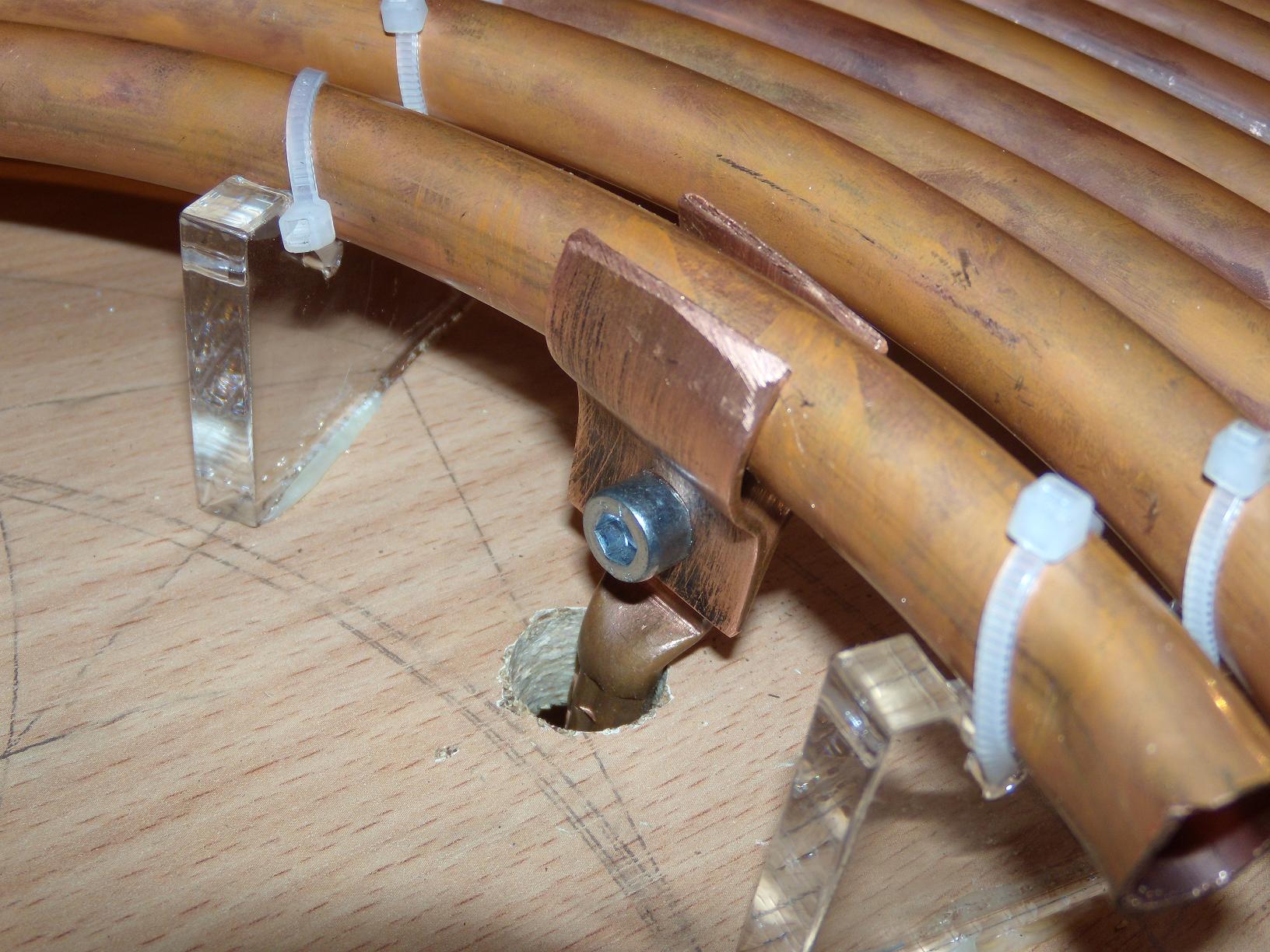
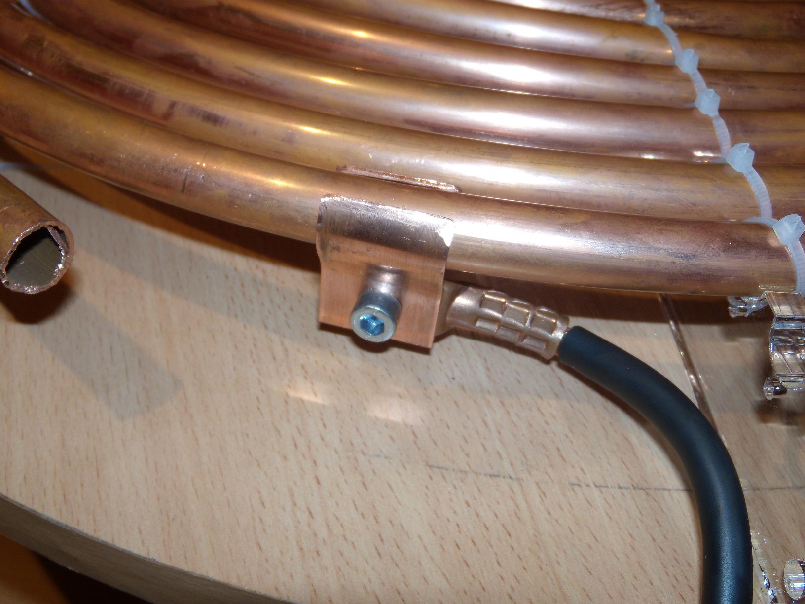
Next, the mechanical part should be projected and the key elements placed etc. The primary winding was the most problematic. After some ideas, by final decision, the winding was flat because of better field distribution at the base of the secondary. The winding was made of soft copper of 15mm diameter and 1mm wall thickness.
Another problem were the brackets attaching the tube to the base. Cutting them with bare hands from plexiglass isn't a good idea, because this material is hard in mechanical treatment. It's better to order it cut with laser or cut the brackets another way.
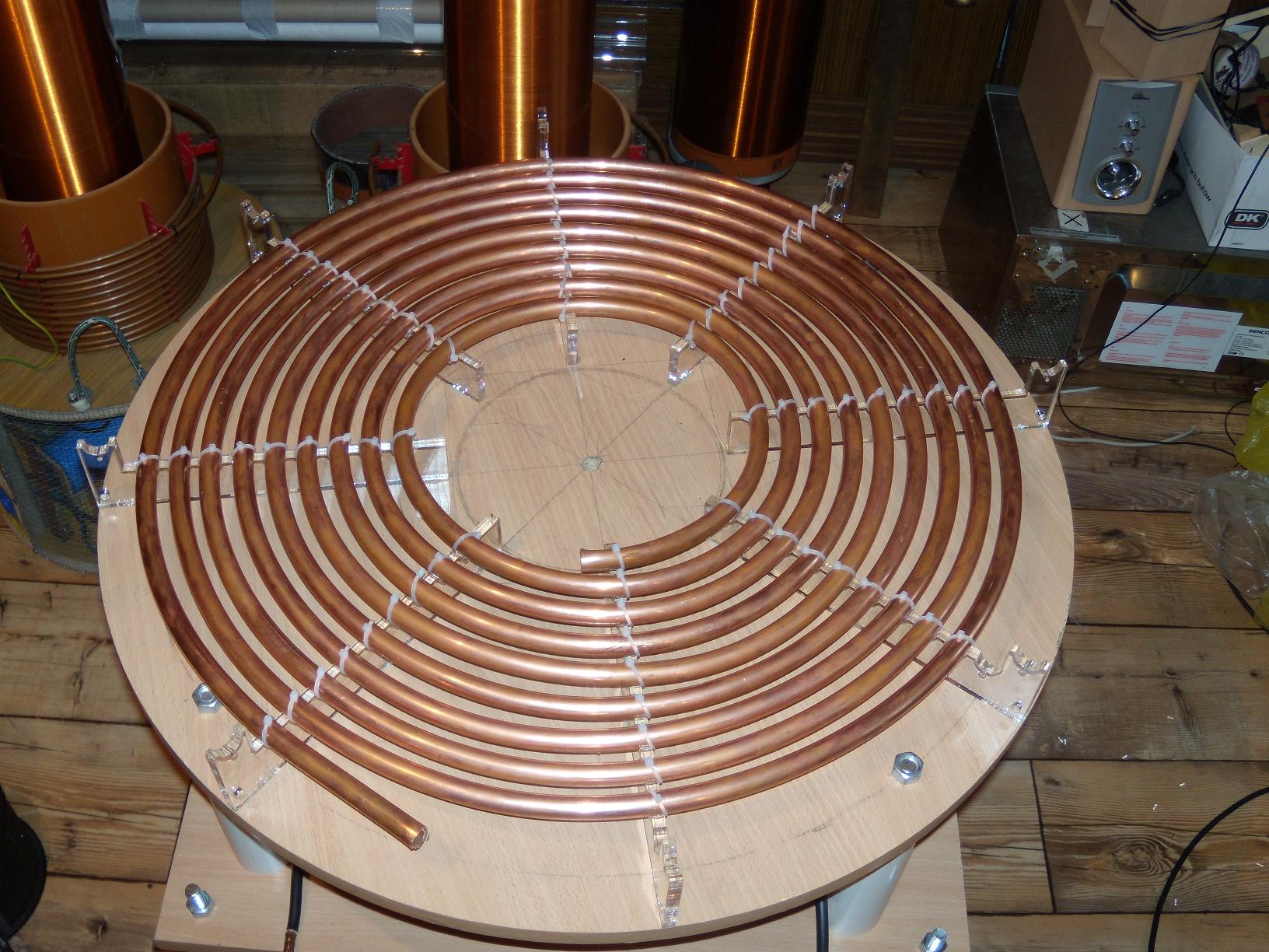
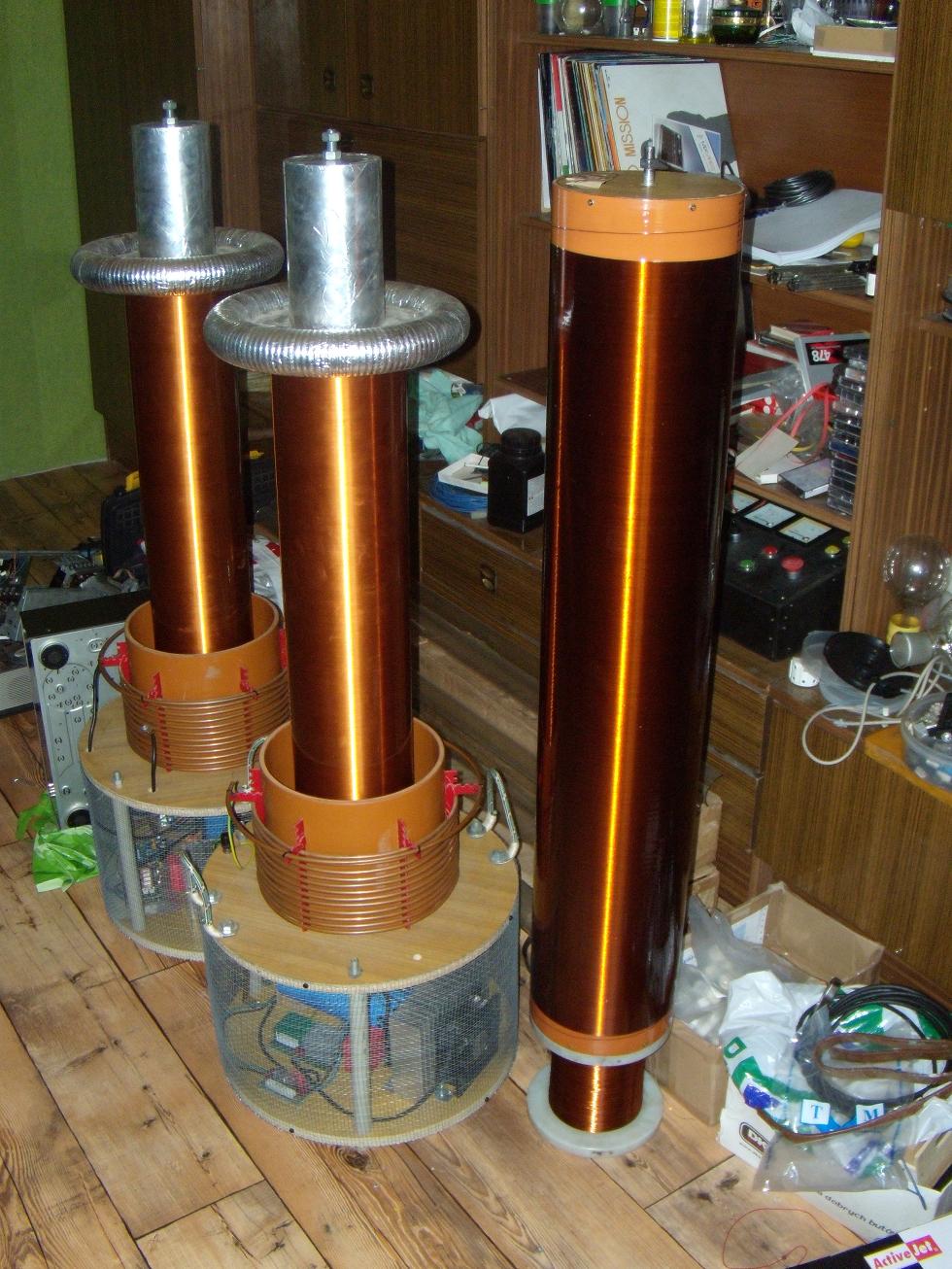
Next important element is the secondary winding. A classic sanitary pipe PVC of 200mm diameter and 1m high was used. The winding has about 2300 wire coils of 0.4mm. It's almost 2kg copper and about 1.5km wire. The winding was lacquered to adhere.
The toroids are also classic construction made of spiroflex ventilation pipes. When using two toroids, the electric field distribution around the windings is improved. That's why sparks are reluctant to get into the primary. Two secure coils – one above and another under the surface of he primary. The upper wire coil is temporary. Eventually, a copper pipe 18mm of 3m long is planned there.
The lower part of the housing with electronics is to be clad with a grid. Now, only a front part is clad.
The powerful transistors need a powerful radiator. It may need milling, because it's surface has to be really smooth. It is additionally supported by two powerful fans 120mm each. It's better to keep the structures at as low temperature as it's possible, that's why a radiator and fans are needed. The radiator is cold while working.
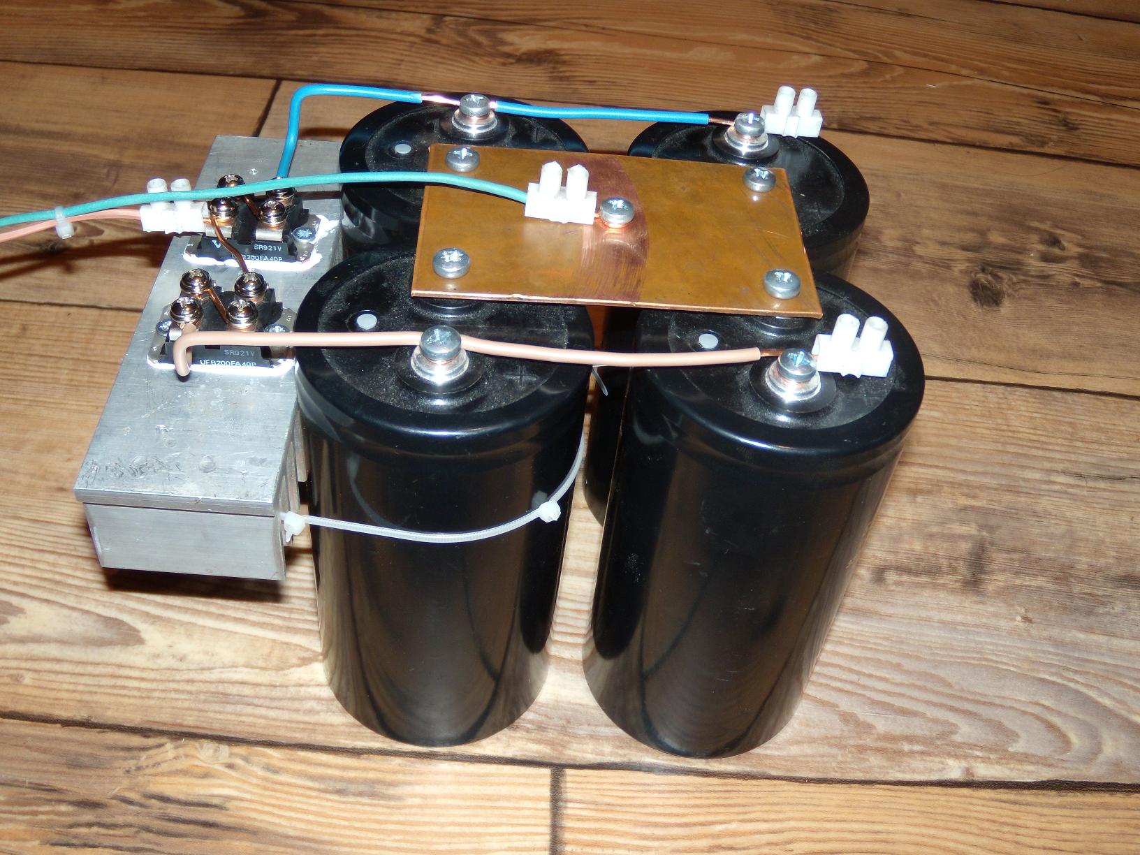
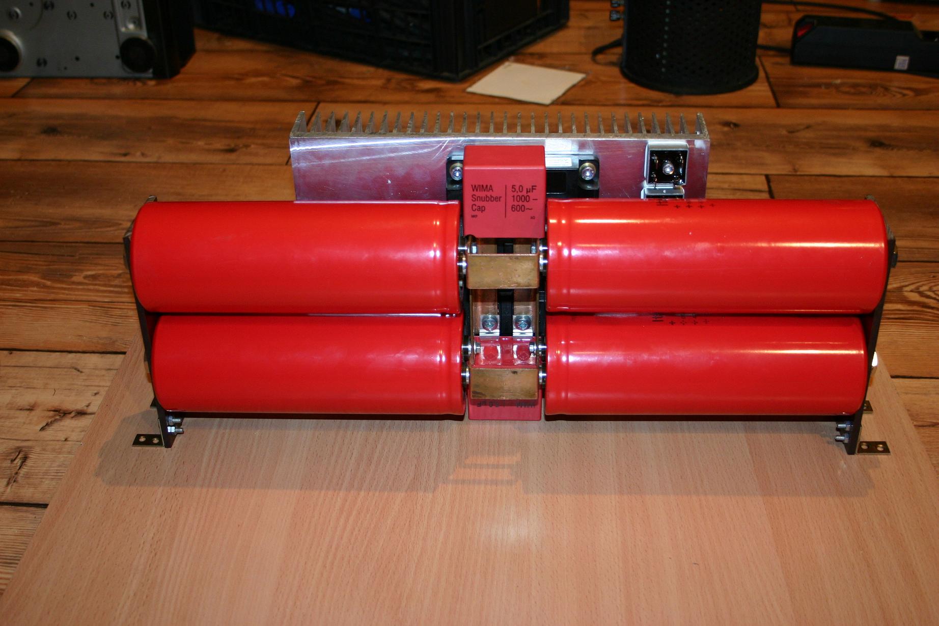
Another key element are the capacitors filtering the power supply. Since the device works in pulses, high electrolytes with a large capacity for pulse – low-impendance ones would be needed.
Powering the bridge was planned to be done by a tension higher than the supply voltage of 320V. It means about 650 700VDC. So that the electrolytes with ability to work with such tension were needed. Because of the fact that the biggest known tension on electrolytes is 500V, it was necessary to link two electrolytes in series. It means half size capacity and the need to use four capacitors.
The electrical/mechanical construction is to minimize the distance between capacitors and transistors and also to enable the use of as big sections as possible. The only disadvantage is the growth of the bridge dimensions width.
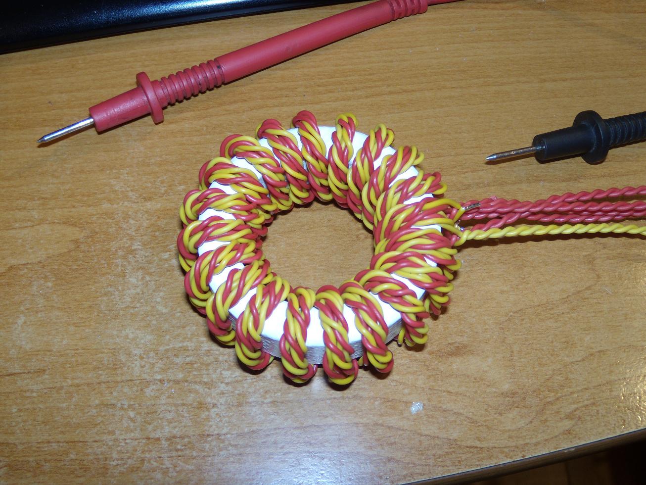
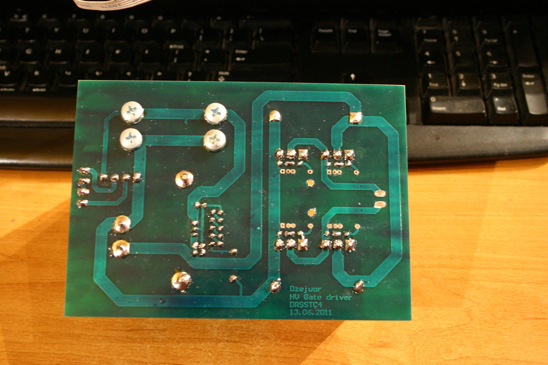
The driver is a predikter powering the medium bridge on mosfets. This time the medium bridge is powered by stabilized tension of 80V. A specially made transformer that controls IGBT transistors gateways was used. The gear of that transformer is 4:1:1:1:1. That constructions allows to reach a typical 20V on gateways. It also decreases the gateways overload time.
Reaching continuous tensions of 650VDC isn't a complicated thing. A voltage doubler is a useful tool to make it. Unfortunately, it has some serious disadvantages. It spoils the shape of the waveform grid.
Next step is building a PCF converter powered by three phases. About 8-10kW should be taken.
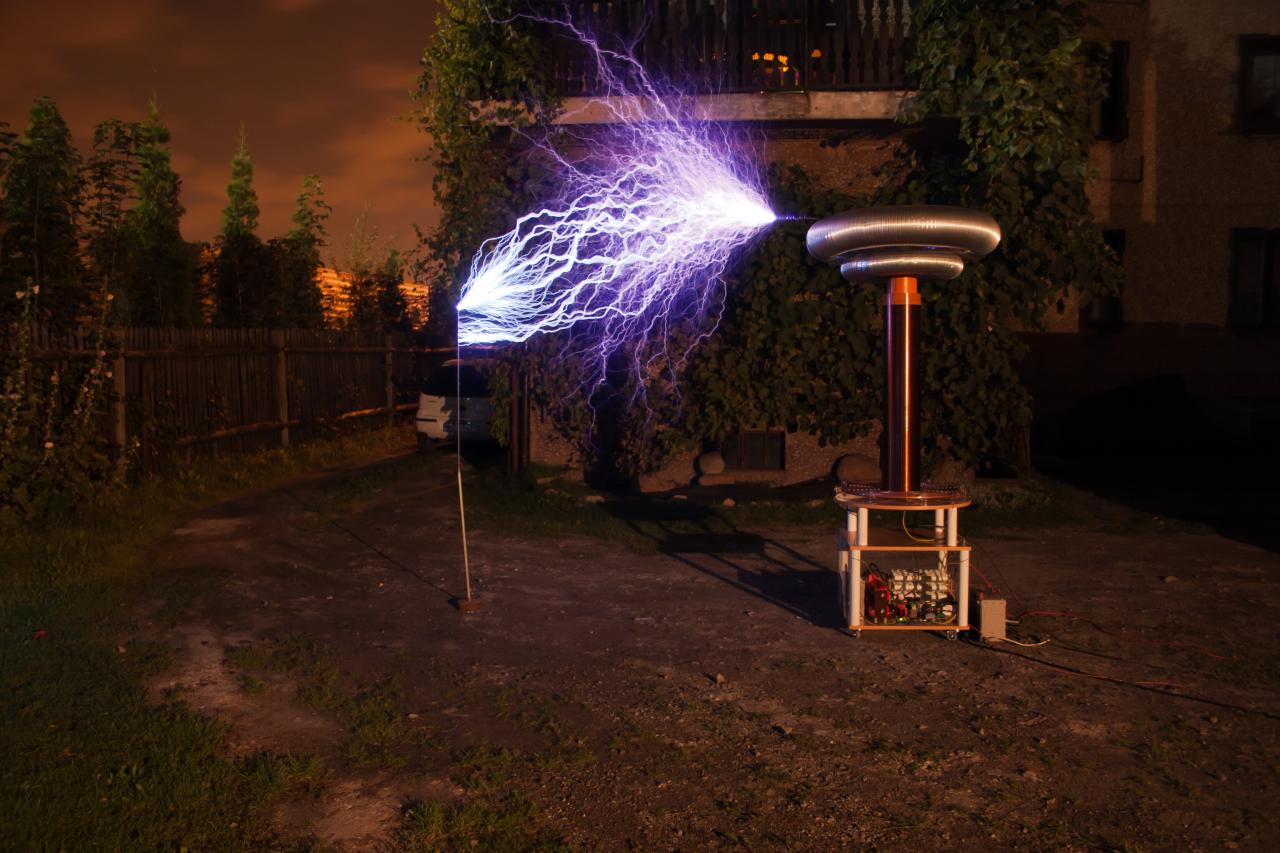
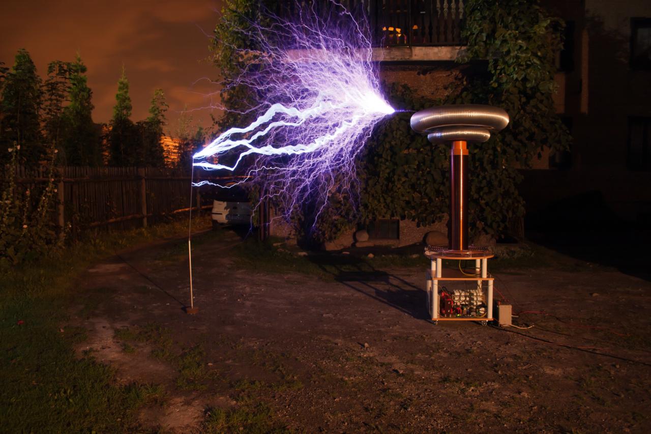
A current limiter in the primary circuit is set on 1400A and it works only when the spark is lit to the ground.
The resonance frequency is about 42kHz.
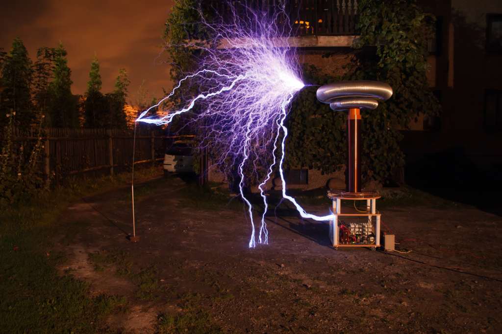
Sparks reached are to 3m. They are really loud and bright.
The whole device is more than 2m high, the diameter of upper toroid is about 1m.


Link to original thread – Ogromna cewka Tesli - DRSSTC4 by Dżejwor