Continue to Site

Welcome to EDAboard.com

Welcome to our site! EDAboard.com is an international Electronics Discussion Forum focused on EDA software, circuits, schematics, books, theory, papers, asic, pld, 8051, DSP, Network, RF, Analog Design, PCB, Service Manuals... and a whole lot more! To participate you need to register. Registration is free. Click here to register now.

a digital potentiometer using mcp4131 and wemos d1 mini dev board

Status
Not open for further replies.

mohamed123

Newbie level 4
Joined
Aug 18, 2021
Messages
7
Helped
0
Reputation
0
Reaction score
0
Trophy points
1
Activity points
66
Hello everyone,
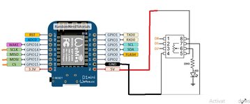
I'm trying to make a digital potentiometer using mcp4131 and wemos d1 mini dev board in order to use it in studying the IV characteristics of a solar cell remotely. The mcp4131 digipot uses SPI communication. I have used a simple Arduino code for testing. the code works correctly with my Arduino Uno, but when i tried it with wemos d1 mini dev board it doesn't work!


code used with arduino :

Code C++ - [expand]
1
2
3
4
5
6
7
8
9
10
11
12
13
14
15
16
17
18
19
20
21
22
23
24
25
26
27
28
29
30
31
32
33
34
35
36
37
38
39
40
41
42
43
44
45
46
47
48
49
50
51
52
53
#include <SPI.h>
 
byte address = 0x00;
int CS= 10;
 
void setup()
{
pinMode (CS, OUTPUT);
SPI.begin();
digitalPotWrite(100)
}
 
void loop()
{
 
}
 
int digitalPotWrite(int value)
{
digitalWrite(CS, LOW);
SPI.transfer(address);
SPI.transfer(value);
digitalWrite(CS, HIGH);
}
 
 
[B]code used with wemos:[/B]
 
#include <SPI.h>
 
byte address = 0x00;
int CS= D8;
 
void setup()
{
pinMode (CS, OUTPUT);
SPI.beginTransaction(SPISettings(5000000, MSBFIRST, SPI_MODE0));
digitalPotWrite(100);
}
 
void loop()
{
 
}
 
int digitalPotWrite(int value)
{
digitalWrite(CS, LOW);
SPI.transfer(address);
SPI.transfer(value);
digitalWrite(CS, HIGH);
SPI.endTransaction();
}


that's the error message that appears on the serial monitor:

ets Jan 8 2013,rst cause:2, boot mode:(3,6)

load 0x4010f000, len 1384, room 16
tail 8
chksum 0x2d
csum 0x2d
v09f0c112
~ld
 
Last edited by a moderator:

Hello!

What do you mean by "I'm trying to make a digital potentiometer using mcp4131"?
The chip itself IS a digital potentiometer.
Can you share the schematic and explain a little bit more what you are doing?
Beside this, you get an error from the serial monitor, but where does the serial monitor
appear in your code?
NB: I don't use Arduino, so it might be an Arduino tool, but anyway, more explanation
would be fine.

Thanks,

Dora
 

That's my circuit diagram.
I'm using the mcp4131 with wemos in order to change the resistance remotely to use it in studying the IV characteristics of a solar panel. I'm using Arduino IDE to program wemos board. The error message appears in the serial monitor of the arduino ide. I made some searching on Google, the error seems to be a software Watchdog resetting, but i can't understand why the wemos reset and how to solve this!
 

Attachments

  • IMG-20210805-WA0020.jpg
    IMG-20210805-WA0020.jpg
    65.6 KB · Views: 621

Hello!

I had a look at your diagram.
I don't understand exactly what you want to do. You want to make the LED vary?
You can try to do the same with a regular potentiometer of the same value first, and you will
notice that you cannot do anything good that way.
1. Supposing you have a red LED, the LED itself drives current from 1.6V only, so it will not
work at all on the low values.
2. Depending of the nominal value of your pot, you will add a fraction of the potentiometer
to your 220 ohm resistor. According to the specs, and supposing I read this right, you can
draw 25 mA from the pot, so it should be enough for one LED, but the behavior will be completely
useless, not linear at all.

-> If you want to dimm the LED, you should try to learn about PWM
-> If you want to do something else, then why not telling us?
-> What is the nominal value of the pot?
-> What do you mean by "it doesn't work"? Could you be a bit more accurate?

Pascal
 
My final aim of the project is to change the resistance remotely (through wifi) in order to study the IV characteristics (voltage versus current at different loads) of a solar panel. I'm using the LED just as an indication for changing the resistance to test the code. Forget about the LED, now i'm reading the output of the potentiometer using the analog pin of an Arduino and also i obtain no change at the output.
 

that's the error message that appears on the serial monitor:
Is this an error messge?
Maybe it´s just some code uploading information.

voltage versus current at different loads
What max voltage and max current are you talking about?
Solar cells are available from milliwatts to kilowatts...

now i'm reading the output of the potentiometer using the analog pin of an Arduino and also i obtain no change at the output.
show your complete schematic. Hand drawn is O.K.

***

Use "Serial.print" to send information to the serial monitor.

Klaus
 

My final aim of the project is to change the resistance remotely (through wifi) in order to study the IV characteristics (voltage versus current at different loads) of a solar panel. I'm using the LED just as an indication for changing the resistance to test the code. Forget about the LED, now i'm reading the output of the potentiometer using the analog pin of an Arduino and also i obtain no change at the output.

Hello!

Well, if you use the analog input, yes, that makes sense. Do you have an oscilloscope at hand? One thing to try next
is to watch the signals. CS, MOSI, MISO, and check if everything is fine. I have used these potentiometers quite a lot,
I don't remember which one, but anyway it was microchip, SPI, 2 channels, potentiometer, and it works exactly as
the datasheet claims, so the only thing I can think about is that the input command stream is wrong.

Dora.
 

yes i can obtain an oscilloscope in my college. but how to use it to check the signals??!
 

Is this an error messge?
Maybe it´s just some code uploading information.


What max voltage and max current are you talking about?
Solar cells are available from milliwatts to kilowatts...


show your complete schematic. Hand drawn is O.K.

***

Use "Serial.print" to send information to the serial monitor.

Klaus
Is this an error messge?
Maybe it´s just some code uploading information.
i googled the message and found that it is an error caused by a watchdog reset

What max voltage and max current are you talking about?
Solar cells are available from milliwatts to kilowatts...
the panel is 60 watt. the open circuit voltage (Voc) is 22.57 V, and the short circuit current (Isc) is 3.58 A.

show your complete schematic. Hand drawn is O.K.
the schematic is attached to the main post.
 

Hi,

Where is the complete schematic? In post#3 there just is a snippet of a wiring diagram. It's not really a schematic.
And I don't think it's complete. Where is the panel? And where is the circuit that can handle 23V and 3.6A?

Klaus

PS: please use the "preview" and to see and corrcet your post before sending it.
 

yes i can obtain an oscilloscope in my college. but how to use it to check the signals??!

Hello!

You need a 4 traces oscilloscope, but if you can't find one, I guess a 2 traces can do it.
1. Plug the CLK and MOSI signals. Also plug CS if it's a 4 traces
-> If it's a 4 traces, use CS down as a sync signal
-> If it's a 2 traces, use clock as as sync signal because you're sure the clock pattern
will not change.
2. Display the signals so that you have one full data frame on the screen.

At this point, if the scope has a SPI analyzer, then add one SPI bus, configure it and you will see
the data code directly on the screen.

If you don't have a SPI analyzer, I guess you will have to work like in the good old days, count the
clocks and write down the data bit by bit. Check if the address is right, etc... Look at the datasheet,
you will find the timings, opcodes, etc...

Dora.
 

Hi,

Where is the complete schematic? In post#3 there just is a snippet of a wiring diagram. It's not really a schematic.
And I don't think it's complete. Where is the panel? And where is the circuit that can handle 23V and 3.6A?

Klaus

PS: please use the "preview" and to see and corrcet your post before sending it.
Aha, i got it now. But the panel and it's specifications aren't my problem now. I'm still trying to just control the mcp4131 digital potentiometer using nodemcu, i'm still in step one and i have problems with it.
 

Hi,

I´m confused what you need. So let´s start with the basics:
* did the WEMOS board ever work (are you sure it is not defective)?
* did you successfully upload another software (like "LED blink") to the WEMOS board?
* did the LED blink?

Klaus
 

Hi,

I´m confused what you need. So let´s start with the basics:
* did the WEMOS board ever work (are you sure it is not defective)?
* did you successfully upload another software (like "LED blink") to the WEMOS board?
* did the LED blink?

Klaus
yes i tried an LED blink software and it worked well
 

Status
Not open for further replies.

Similar threads

Part and Inventory Search

Welcome to EDABoard.com

Sponsor

Back
Top