Continue to Site

Welcome to EDAboard.com

Welcome to our site! EDAboard.com is an international Electronics Discussion Forum focused on EDA software, circuits, schematics, books, theory, papers, asic, pld, 8051, DSP, Network, RF, Analog Design, PCB, Service Manuals... and a whole lot more! To participate you need to register. Registration is free. Click here to register now.

[PIC] 7seg (common anode) temperature sensor controlled by LM35 & PIC18F4520

Status
Not open for further replies.
Hello Brian.

Thank you for your vast explanations.

I did change reference voltage for ADC from 5VDC to 1.5VDC using resistive voltage divider and fed it to PORTA.3 I also changed ADCON1 value accordingly to 0x1e.

I did this in code for LCD display:

Code:
Waitms 2000
Adcin 0,x
x = x * 150
x = x / 1023
LCDOUT "Temp: ",#x

Bad results with no sequencing ever took place.
It showed 40 on LCD.

Thank you
 

Added:

I've found on https://extremeelectronics.co.in/mi...-temperature-sensor-with-pic-microcontroller/ the following C code:

Code:
#include <htc.h>

#include <math.h>

#include "lcd.h"

//Chip Settings
__CONFIG(1,0x0200);
__CONFIG(2,0X1E1F);
__CONFIG(3,0X8100);
__CONFIG(4,0X00C1);
__CONFIG(5,0XC00F);


//Simple Delay Routine
void Wait(unsigned int delay)
{
   for(;delay;delay--)
      __delay_us(100);
}

//Function to Initialise the ADC Module
void ADCInit()
{
   //We use default value for +/- Vref

   //VCFG0=0,VCFG1=0
   //That means +Vref = Vdd (5v) and -Vref=GEN

   //Port Configuration
   //We also use default value here too
   //All ANx channels are Analog

   /*
      ADCON2

      *ADC Result Right Justified.
      *Acquisition Time = 2TAD
      *Conversion Clock = 32 Tosc
   */

   ADCON2=0b10001010;
}

//Function to Read given ADC channel (0-13)
unsigned int ADCRead(unsigned char ch)
{
   if(ch>13) return 0;  //Invalid Channel

   ADCON0=0x00;

   ADCON0=(ch<<2);   //Select ADC Channel

   ADON=1;  //switch on the adc module

   GODONE=1;//Start conversion

   while(GODONE); //wait for the conversion to finish

   ADON=0;  //switch off adc

   return ADRES;
}
void main()
{
   //Let the LCD Module start up
   Wait(100);

   //Initialize the LCD Module
   LCDInit(LS_BLINK);

   //Initialize the ADC Module

   ADCInit();

   //Clear the Module
   LCDClear();

   //Write a string at current cursor pos
   LCDWriteString("LM35 Test");
   LCDWriteStringXY(4,1,"Degree Celcius");

   while(1)
   {
      unsigned int val; //ADC Value

      unsigned int t;      //Temperature


      val=ADCRead(0);   //Read Channel 0

      t=round(val*0.48876);//Convert to Degree Celcius

      LCDWriteIntXY(0,1,t,3);//Prit IT!


      Wait(1000);
   }

}

And gave it a try on my breadboard. It worked in excellent manner.
 

The difference is in this line:
t=round(val*0.48876);//Convert to Degree Celcius
It uses a fractional multiplier, the value 0.48876, which Oshonsoft Basic will not accept because it only understands whole (integer) numbers. The math trick I used was to scale the numbers up so the fraction part gave a smaller error.

You still need to look at the routines for comparing the result. Instead of checking if the value is between limits at each stage, I would do it this way:
1. is it below the lower limit? ---> fail
2. is it above the upper limit? ----> fail
3. it must be a pass.

That way removes some of the calculations, making the program smaller and faster.

Brian.
 
Thank you Brian.

THREE notes to be taken into consideration:

1) The user set the value for ADCON2 to "0b10001010" , and said that ADCON1 is by default set to VDD as Vref so he won't make any changes to it. We didn't put any value for that register, nor we did anything to ADCON0. Isn't all ADC operations within PIC must be set using the three AD registers ADCON0, ADCON1, ADCON2?

2) The mikroC compiler have a pre-defined 7 seg control GUI. Can we continue the C code but instead of sending it to LCD, show it on common anode 7seg?

3) While the user used VDD of 5 volts, it still showed accurate weather temperature level on LCD.
 

@betwixt

Hello,

The circuit is terribly bad. The switching on/off techniques of the segments shouldn't be done this way. LEDs are having bad times being switched on or off using the BJT. Regardless of the code, there must be readily made IC based drivers to turn them on or off. I haven't been introduced to any.

About the ADC, I've found the last solution and optimum one, using Oshonsoft Define directives as Define ADC_CLOCK and other one referring to ADC sampling time that were by default set to values very far from Tad and Fosc recommended by Microship (page 249 of PIC18f4520 datasheet). I've tried the results on LCD, and saw best of all values, they were not that exact since Tconv that must be set on 2.4uS (as Microship recommends) cannot be set on Oshonsoft either 2 or 3.

Do you have any solutions/comments about the hardware and perhaps some methods to improve it?


Thanks
 

There is a common and inexpensive driver that is ideally suited to this job, the ULN2803 but it is hugely over rated for driving display segments. I suggest just rewiring your existing circuit like this:

NPN transistors
Emitters directly to 0V
Bases driven from PIC through 2200 (2.2K) resistors
Collects to segments through 270 Ohm resistors.

Assuming the transistors have a gain of about 100, that should fully saturate them and make the segments pass about 15mA each.

If you can, run one regulator for the display (although within reason it doesn't have to regulated at all) and a different regulator for the PIC. The reason for that is the display current can vary from 60mA (15mA * 2 segments * 2 digits) if '11' is displayed right up to 210mA if '88' is displayed and that mighgt cause a slight variation in the regulator output. Inside the PIC, if the ADC uses VDD as it's reference or if the reference is divided down from VDD, the reading will change if VDD changes.

I did a design a few years ago that used a PIC with VDD as the reference and couldn't work out why some units worked and some others didn't, my investigation found the 7805 voltage regulators were the problem. They were all well within the manufacturers specification but the slight differences in output voltage made the ADC produce different results. Based on the problems that caused, I would urge you to make sure your VDD at the PIC is as stable as possible!

Brian.

Thank you Brian!

In the matter of fact, all your recommendations are already done!!
The rewiring are as you stated, BJTs connections also, and two regulators 7805 are used, one for PIC and LM35 other for seven segments display.

Still, not functioning as should be. Although I've connected 2uF electrolytic in parallel with 10nF ceramic to both Vdd and Vss pins of the PIC > sometimes the entire circuit doesn't turn on, sometimes function good, other times function with one or two LED segments turned off, while they should be on.


Thank you
 

Hello Brian and thanks a lot@!

Code:
Define CLOCK_FREQUENCY = 20
Define ADC_SAMPLEUS = 2
Define ADC_CLOCK = 0

Dim x As Long

main:
	
	WaitMs 500
	Adcin 0, x
	WaitMs 500
	x = x * 500
	x = x / 1023
	
	Gosub checktemp
	Goto main
End                                               

checktemp:
	If x = 4 Then
		High PORTB.0
		High PORTB.1
		High PORTB.3
		High PORTB.5
		High PORTB.6
		High PORTB.7
		Low PORTB.2
		Low PORTB.4
	
		High PORTC.2
		High PORTC.3
		High PORTC.5
		High PORTC.7
		Low PORTC.0
		Low PORTC.1
		Low PORTC.4
		Low PORTC.6
	Endif
	
	If x = 5 Then
		High PORTB.0
		High PORTB.1
		High PORTB.3
		High PORTB.5
		High PORTB.6
		High PORTB.7
		Low PORTB.2
		Low PORTB.4
	
		High PORTC.2
		High PORTC.3
		High PORTC.6
		High PORTC.7
		High PORTC.1
		Low PORTC.0
		Low PORTC.1
		Low PORTC.5
		Low PORTC.6
	Endif
	
	If x = 6 Then
		High PORTB.0
		High PORTB.1
		High PORTB.3
		High PORTB.5
		High PORTB.6
		High PORTB.7
		Low PORTB.2
		Low PORTB.4
	
		High PORTC.6
		High PORTC.7
		High PORTC.0
		High PORTC.1
		High PORTC.2
		High PORTC.3
		Low PORTC.4
		Low PORTC.5
	Endif
	
	If x = 7 Then
		High PORTB.0
		High PORTB.1
		High PORTB.3
		High PORTB.5
		High PORTB.6
		High PORTB.7
		Low PORTB.2
		Low PORTB.4
	
		High PORTC.6
		High PORTC.5
		High PORTC.2
		High PORTC.3
		Low PORTC.0
		Low PORTC.1
		Low PORTC.4
		Low PORTC.7
	Endif
	
	If x = 8 Then
		High PORTB.0
		High PORTB.1
		High PORTB.3
		High PORTB.5
		High PORTB.6
		High PORTB.7
		Low PORTB.2
		Low PORTB.4
	
		High PORTC.6
		High PORTC.7
		High PORTC.0
		High PORTC.1
		High PORTC.2
		High PORTC.3
		Low PORTC.4
		High PORTC.5
	Endif

	If x = 9 Then
		High PORTB.0
		High PORTB.1
		High PORTB.3
		High PORTB.5
		High PORTB.6
		High PORTB.7
		Low PORTB.2
		Low PORTB.4
	
		High PORTC.6
		High PORTC.7
		High PORTC.5
		High PORTC.1
		High PORTC.2
		High PORTC.3
		Low PORTC.4
		Low PORTC.0
	Endif
	
	If x = 10 Then
		High PORTB.0
		Low PORTB.1
		Low PORTB.3
		High PORTB.5
		Low PORTB.6
		Low PORTB.7
		Low PORTB.2
		Low PORTB.4
	
		High PORTC.6
		High PORTC.7
		High PORTC.0
		High PORTC.1
		Low PORTC.2
		High PORTC.3
		Low PORTC.4
		High PORTC.5
	Endif
	
	If x = 11 Then
		High PORTB.0
		Low PORTB.1
		Low PORTB.3
		High PORTB.5
		Low PORTB.6
		Low PORTB.7
		Low PORTB.2
		Low PORTB.4
	
		Low PORTC.6
		Low PORTC.7
		High PORTC.0
		Low PORTC.1
		Low PORTC.2
		Low PORTC.3
		Low PORTC.4
		High PORTC.5
	Endif
	
	If x = 12 Then
		High PORTB.0
		Low PORTB.1
		Low PORTB.3
		High PORTB.5
		Low PORTB.6
		Low PORTB.7
		Low PORTB.2
		Low PORTB.4
	
		High PORTC.6
		High PORTC.5
		High PORTC.2
		High PORTC.0
		Low PORTC.4
		High PORTC.1
		Low PORTC.3
		Low PORTC.5
	Endif
	
	If x = 13 Then
		High PORTB.0
		Low PORTB.1
		Low PORTB.3
		High PORTB.5
		Low PORTB.6
		Low PORTB.7
		Low PORTB.2
		Low PORTB.4
	
		High PORTC.6
		High PORTC.2
		Low PORTC.0
		High PORTC.1
		Low PORTC.7
		High PORTC.3
		Low PORTC.4
		High PORTC.5
	Endif
	
	If x = 14 Then
		High PORTB.0
		Low PORTB.1
		Low PORTB.3
		High PORTB.5
		Low PORTB.6
		Low PORTB.7
		Low PORTB.2
		Low PORTB.4
	
		High PORTC.2
		High PORTC.3
		High PORTC.5
		High PORTC.7
		Low PORTC.0
		Low PORTC.1
		Low PORTC.4
		Low PORTC.6
	Endif
	
	If x = 15 Then
		High PORTB.0
		Low PORTB.1
		Low PORTB.3
		High PORTB.5
		Low PORTB.6
		Low PORTB.7
		Low PORTB.2
		Low PORTB.4
	
		High PORTC.2
		High PORTC.3
		High PORTC.6
		High PORTC.7
		High PORTC.1
		Low PORTC.0
		Low PORTC.1
		Low PORTC.5
		Low PORTC.6
	Endif
	
	If x = 16 Then
		High PORTB.0
		Low PORTB.1
		Low PORTB.3
		High PORTB.5
		Low PORTB.6
		Low PORTB.7
		Low PORTB.2
		Low PORTB.4
	
		High PORTC.6
		High PORTC.7
		High PORTC.0
		High PORTC.1
		High PORTC.2
		High PORTC.3
		Low PORTC.4
		Low PORTC.5
	Endif
	
	If x = 17 Then
		High PORTB.0
		Low PORTB.1
		Low PORTB.3
		High PORTB.5
		Low PORTB.6
		Low PORTB.7
		Low PORTB.2
		Low PORTB.4
	
		High PORTC.6
		High PORTC.5
		High PORTC.2
		High PORTC.3
		Low PORTC.0
		Low PORTC.1
		Low PORTC.4
		Low PORTC.7
	Endif
	
	If x = 18 Then
		High PORTB.0
		Low PORTB.1
		Low PORTB.3
		High PORTB.5
		Low PORTB.6
		Low PORTB.7
		Low PORTB.2
		Low PORTB.4
		
		High PORTC.6
		High PORTC.7
		High PORTC.0
		High PORTC.1
		High PORTC.2
		High PORTC.3
		Low PORTC.4
		High PORTC.5
	Endif
		
	If x = 19 Then
		High PORTB.0
		Low PORTB.1
		Low PORTB.3
		High PORTB.5
		Low PORTB.6
		Low PORTB.7
		Low PORTB.2
		Low PORTB.4
		
		High PORTC.6
		High PORTC.7
		High PORTC.5
		High PORTC.1
		High PORTC.2
		High PORTC.3
		Low PORTC.4
		Low PORTC.0
	Endif
	
	If x = 20 Then
		High PORTC.6
		High PORTC.5
		High PORTC.2
		High PORTC.0
		Low PORTC.4
		High PORTC.1
		Low PORTC.3
		Low PORTC.5
				
	High PORTB.0
		High PORTB.1
		High PORTB.3
		High PORTB.5
		High PORTB.6
		High PORTB.7
		Low PORTB.2
		Low PORTB.4

	Endif
Return

Above is the BASIC code

thanks again
 

Thanks, a question for you that will help me:
Can you tell me what the LEDs should display for each of the values of 'x' from 4 to 20, it will save me having to work out which port bits are connected to each segment.

Brian.
 
Thanks, a question for you that will help me:
Can you tell me what the LEDs should display for each of the values of 'x' from 4 to 20, it will save me having to work out which port bits are connected to each segment.

Brian.

Sure thing dear, here is a describing photo:


Thank you
 

I`m really sorry for any inconveniences dear Brian.

According to your image, we have two of them. One to the left, other to the right.
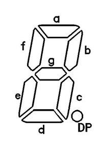
The left one has the following pin out:
a: PORTB.1
b: PORTB.0
c: PORTB.5
d: PORTB.6
e: PORTB.7
f: PORTB.3
g: PORTB.2
DP: PORTB.4

The right one has the following pin out:
a: PORTC.6
b: PORTC.5
c: PORTC.3
d: PORTC.1
e: PORTC.0
f: PORTC.7
g: PORTC.2
DP: PORTC.4

Thank you
 

Some errors in the port bits there!
Try this:
Code:
Define CLOCK_FREQUENCY = 20
Define ADC_SAMPLEUS = 2
Define ADC_CLOCK = 0

Dim x As Long
Dim lsd As Byte
Dim msd As Byte

main:
    TRISB = 0
    TRISC = 0

loop:
    WaitMs 500
    Adcin 0, x
    WaitMs 500
    x = x * 500
    x = x / 1023
'put some limits checking here!
    msd = x / 10
    lsd = x Mod 10
    
    Gosub checktemp
    Goto loop
End                                               

checktemp:
    LATB = LookUp(0xeb, 0x21, 0xc7, 0x67, 0x2d, 0x6e, 0xee, 0x23, 0xef, 0x6f), msd
    LATC = LookUp(0xeb, 0x28, 0x67, 0x6e, 0xac, 0xce, 0xcf, 0x68, 0xef, 0xee), lsd
    Return

Added bonus: it compiles to 776 bytes instread of 2,294!

Brian.
 
Thank you Brian!

I tried that code using lookup function.

for an actual temp degree of 15C it showed different fluctuating values between 35 to 44.

the problem of missing segments from getting on is gone. the problem is about decimal converted values. perhaps subtraction/addition is needed?

thanks a lot
 

Hi,

I can imagine some problems:
* maybe the ADC Vref is not correct / not stable. (This causes gain error)
* maybe you have Ground bounce between ADC_GND and LM35_GND. (This causes offset error)
The later is more likely, especially because it is fluctuating. Maybe caused by currents of periferals like your display.
--> Avoid ADC gnd currents. Connect the LM35 exactely at the ADC GND pin.

If you have lengthy wires to the LM35:
* use RC filtering at the temperature signal with a tau of about 0.1s ... 2s
* use digital filtering (averaging, low pass...)
* use differential voltage measurement with a GND_sense at LM35.

Klaus
 

I'm glad the segment problem has gone away. What I did was treat the digits as tens and units instead of using a different segement patterns for each value. It makes the code smaller and it also works over the whole range of 00 to 99 instead of just the values you catered for.

The remaining problem can be due to two things - either the voltage really is fluctuating as Klaus suggests or the ADC is not able to sample fast enough.

The most likely, is voltage fluctuations, the LM35 only produces 10mV/C output voltage so for the reading to vary between 35 and 44 implies there is an offset of ~25mV somewhere and a variation of about 90mV. The most likely culprit it the display itself as it draws most current by far and it varies most from one digit to another. You can get a kind of feedback where the number being displayed causes the voltage drop to change which in turn makes the number change again. As the ADC input current is very low, I suggest an RC filter is a good way of confirming this. It will not fix the problem but it should demonstate the cause, try adding a resistor of about 4.7K between the LM35 output and the ADC input and add a capacitor of about 1uF between the ADC input and VSS. It is important that the capacitor goes as close as possible to the PIC pins. If the reading still changes (expected) but much more slowly, it means you have voltage drop in the wiring between the LM35 and PIC which you need to eliminate. In all circuits like this where small analog voltages are being measured, you have to be extremely careful where the current paths are so you don't inadvertantly drop voltages along them.

If the ADC is the problem, try adding "ADCON2 = 0xBE" after the line "TRISC = 0". It will make the ADC run as slowly as possible to prove the point. The numbers used by the compiler don't really mean anything but setting ADCON2 to that value will force the slowest clock and longest conversion time.

Brian.
 

Status
Not open for further replies.

Similar threads

Part and Inventory Search

Welcome to EDABoard.com

Sponsor

Back
Top