Continue to Site

Welcome to EDAboard.com

Welcome to our site! EDAboard.com is an international Electronics Discussion Forum focused on EDA software, circuits, schematics, books, theory, papers, asic, pld, 8051, DSP, Network, RF, Analog Design, PCB, Service Manuals... and a whole lot more! To participate you need to register. Registration is free. Click here to register now.

74HC14 issues please HELP!

Status
Not open for further replies.

SAWULA

Newbie level 6
Joined
Nov 11, 2009
Messages
11
Helped
0
Reputation
0
Reaction score
0
Trophy points
1,281
Activity points
1,378
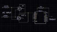
I have two built circuits and I am trying to integrate them. In one ciruit there is 74HC14 IC and there is a 2.2k resister between two gates (pin2 and pin 3) and in other circuit they are directly connected (pin1 and 2). I want to know why is 2.2k resister used? I know the purpose is to invert the output of first gate but why we can't directly connect those pins in both cases?
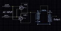
 

in other circuit they are directly connected (pin1 and 2)
You won't want to directly connect pin1 and 2 of HC14... (unless designing an unreliable oscillator)
 

You won't want to directly connect pin1 and 2 of HC14... (unless designing an unreliable oscillator)
Actually he said pins 2 and 3 (output to input)

I don't know the exact circuit but you can connect the gates directly without a problem, the resistor doesn't change the state between the gates.

Alex
 

nice... It helps to my assign..

---------- Post added at 16:13 ---------- Previous post was at 16:09 ----------

Good day everyone.! Anyone can help me on my project? ''Eye detection sensor: a developmental research on alert system for drivers fatigue.'' my plan is to use a camera to m0nitor the m0vement of the iris but i d0nt knw how will i start., please i really need it...
 

Sorry for the mistake. I wanted to say pin2 and pin3. The two circuits are x10 transmitter and a x10 receiver. 74HC14 is used to detect the zero crossings of the AC power lines. (x10 is a protocol that is used to communicate over power lines) And I want to combine both transmitter and the receiver together and create a transceicver. In the transmitter ciruit pin2 and pin3 of 74HC14 is directly connected and in the receiver circuit they are connected through a 2.2k resister. I want know the difference inbetween so that I can use either directly connection or the connection through 2.2k resister for my combined transceicver circuit.


The only possible reason for using the resistor is to introduce a tiny delay in the signal but it would be so insignificant at power line frequency as to be useless. In some designs a resistor is used to isolate a driving signal from the pin it drives so test signals can be injected or the logic gate can be tested in-circuit.

Your schematic seems to be missing a pull-up resistor on pin 1 and a ground on the opto-couplers. Wouldn't it be a better and cheaper solution to use a bridge rectifier and one opto?

Brian.
 

Status
Not open for further replies.

Part and Inventory Search

Welcome to EDABoard.com

Sponsor

Back
Top