Continue to Site
Follow along with the video below to see how to install our site as a web app on your home screen.
Note: This feature may not be available in some browsers.
if( up_push){
        	_delay_cycles(50-1);
        	while(up_push);


        	if(++up == 10)up = 0;

        	switch(setCounter){
        	case 0:
        		display[0]=display[0];
        		display[1]=display[1];
        		display[2]=display[2];
        		display[3]=display[3];
        		display[4]=display[4];
        	case 1:
        		display[4]=capture[up];
        		break;
        	case 2:
        		display[3]=capture[up];
        		break;
        	case 3:
        		display[2]=capture[up];
        		break;
        	case 4:
        		display[1]=capture[up];
        		break;
        	case 5:
        		display[0]=capture[up];
        		break;
        	default: break;
        	}

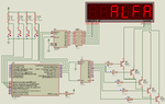
@SunnySkyGuy , yes, i've solved the ghosting problem. It was because of code error. But, there is new concern i do not really understand the current value that flows in my circuit. It is 7mA or 8mA while blinking. Is it too low for 5 digit ? It is DC current but, if each digit's standart working current is 15mA should it been 75mA DC ?
I've used CD4017BE, TPIC5b695, 2N3904(npn bjts) also 100 ohm for each digit on emmitter to led. Display brightness can be seen while sunny even draw 8mA from the source ?
Thanks in advance.
If i try for -12.34 the one or two segment of digit which is with "dot point" are ghosting. Furthermore, if i write 123 to number it is displayed as "12300"