Continue to Site

Welcome to EDAboard.com

Welcome to our site! EDAboard.com is an international Electronics Discussion Forum focused on EDA software, circuits, schematics, books, theory, papers, asic, pld, 8051, DSP, Network, RF, Analog Design, PCB, Service Manuals... and a whole lot more! To participate you need to register. Registration is free. Click here to register now.

60 Hz hum. How to get rid of it. Any suggestions.

Status
Not open for further replies.

obrien135

Full Member level 5
Joined
Nov 10, 2009
Messages
240
Helped
5
Reputation
10
Reaction score
5
Trophy points
1,298
Location
Connecticut
Activity points
3,259
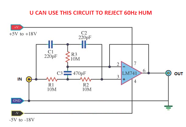
To remove 60Hz hum from supply can you put a big cap across the supply? I am using a radio shack battery eliminator as the supply. Would an LM7812 circuit yield a cleaner DC? Wouldn't there be some kind of wallpack that I could use?

George
 

Using capacitors across DC cupply line will reduce hum to most of the extent. Using RF choke in addition too will help futher. Try using 4700 MFd 50 volts or 2200 Mfd 50 volts and take care of polarity while connecting. LM7812 is a volatge regulator which will regulate the input voltage to 12 when the input is at least 15 or more, and is not a filtering device. Thus using this may not help reducing Hum.
If you are serious about experimenting, and require a good voltage source, instaed using the plugpack, you may go in for better quality, regulated Lab power supply which is variable from 0-30 volts with 2-3 amps of current with digital displays, available at most of the electronic vendors.
In case you are intretsed, Here is a full project of a 0-30 volts Lab supply
https://www.edaboard.com/threads/189313/
 
If the hum is there only on one channel and only when the volume pot for that channel is at a certain setting, is that indicative of some other type of problem?
 

If the hum is there only on one channel and only when the volume pot for that channel is at a certain setting, is that indicative of some other type of problem?

actually r u telling about a stereo channel?
I think the hum will affect both channels equally, but if the channels are of different gain and different equalizer settings, then also u could feel the difference in hum.
More over, for an amplifier, the connections taken from the POT, input sockets etc should use coaxial wires. This could reduce some noise. If one input wire is little bit more longer then also u could feel some difference in noise.

---------- Post added at 09:20 ---------- Previous post was at 07:20 ----------

33_1286356827.png
 
Thanks for the circuit diagram. I will try it. When you mentioned that hum could occur when the gain is different, does this mean the gain af an individual stage or could it also be the overall gain of the channel including the attenuation of the volume pot? It is a stereo amp.
 

overall gain, i think so...am not sure now..
ok, when u make the pot to zero volume position, then could u feel any difference in hum level?

---------- Post added at 09:59 ---------- Previous post was at 09:47 ----------

am not telling that gain difference is a reason or cause for hum. Since u told in one channel there is more hum, so i replied like that.
 
I like thie circuit,thank you!
 

Since the signal you are referring to is fully rectified from a 60 Hz sine wave, it presents as a 120 Hz ripple.
 

I've never seen an op amp circuit with both inputs connected to the same network and neither having a path to ground. I was trying to psych out the circuit, but I couldn't quite figure out how it works as a notch filter. Can you explain it to me? I know what a notch filter is, just not how this one works. I can see that there is a zero at about 34Hz and then a pole at about 72 Hz, but I don't quites understand the dynamics of how the circuit works.The only reason I can tell that the lower one ia a zero and the other a pole is because it's supposed to be a notch filter.

George
 
Last edited:

ok, when u make the pot to zero volume position, then could u feel any difference in hum level?


---------- Post added at 09:59 ---------- Previous post was at 09:47 ----------


Actually, When I lower one of the pots (there's one for each channel; ganged pots are too expensive) that's when the hum starts. When I return the pot to the position just before where the hum started, it stops.
 

R U SURE THE NOISE IS THE 60Hz HUM?
HAD U EVER TESTED THE AMP WITH BATTERY?
WHICH IC U R USING?
IS THERE ANY CAPACITOR CONNECTED BETWEEN THE POWER AMP INPUT AND POT OUTPUT?
IS UR POWER AMP ISs HEAT SINK PERFECTLY GROUNDED?
IS THE TRANSFORMER BODY PERFECTLY GROUNDED?
 

I was trying to psych out the circuit, but I couldn't quite figure out how it works as a notch filter. Can you explain it to me?

Hi George,
It's rather simple:
* As a first step, imagine node 2 is grounded. In this case you have a classical passive bandstop filter (double-T toplogy) with a very bad selectivity.
* This can be improved using active positive feedback (see the Sallen-Key principle which is based on the same effect of pole-Q enhancement). Therefore, the output of the passive network is connected to an unity gain amplifier and the amplifier output fed back to the corresponding common node of the RC network.
 
Op amp twin T notch filter circuit with variable Q

The twin T notch filter with variable Q is a simple circuit that can provide a good level of rejection at the "notch" frequency. It uses two operational amplifiers in the circuit, and the twin "T" section can be seen between the two operational amplifiers.

The variable Q function for the twin T notch filter is provided by the potentiometer placed on the non-inverting input of the lower operational amplifier in the diagram.
86_1286452464.gif

Calculation of the value for the circuit is very straightforward. The formula is the same as that used for the passive version of the twin T notch filter.

fc = 1 / (2 pi R C)

Where:
fc = cut off frequency in Hertz
pi = 3.142
R and C are the values of the resistors and capacitors as in the circuit

The notch filter circuit can be very useful, and the adjustment facility for the Q can also be very handy. The main drawback of the notch filter circuit is that as the level of Q is increased, the depth of the null reduces. Despite this the notch filter circuit can be successfully incorporated into many circuit applications.
 
This would be my choice also.
I did something very similar some years ago for an EEG design that
needed to work in both 50 and 60 Hz areas.
Using good quality op amps (for that particular application) was essential
but it was cheaper/lighter and more flexible than any other solution I found.

I'd say save yourself some agro and just go with vinodstanur's nice design.

john
 
It sounds like 60Hz but I could be mistaken.

I haven't tried it with a battery yet.

I'm using 2N3904 transisters, not IC's.

Yes there is a cap between the amp input and the pot, but it's not a power amp. It is driving a 47Kohm load.

At this point the only transformer is in the battery eliminator that I am using for power. It has an unbalanced input and output.

---------- Post added at 14:03 ---------- Previous post was at 13:59 ----------

OK, thanks fellows.
 

47K load??!!!(what is that)
could u pls upload ur circuit diagram?
voltage of the source?
 
Last edited:

It's an AUX input on a CD player. The schematic is at a friends house. I'll have to scan it but it'll take a few days. The 47Kohms is what I measured with power off, but it might be didderent with power on.
 

First, determine if the hum is from the power supply or the input signal. Swap in a battery as the supply or try a battery powered input to make this determination. Make sure your signal input is shielded and that the shield is connected to the same ground point as the amplifier.
 

Hum caused by battery eliminator output voltage ripple should be 120Hz. If it is 60Hz then your battery eliminator is defective (one of diodes in rectifier is broken). Most often cause for 60Hz hum are ground problems with your audio equipement. Ground potentials (chassis potentials) for audio equipement are different (sound source, amplifier), they are not connected, grounded in one point and thus between grounds flows 60Hz current causing the hum in audio. I presume you are using PC as sound source.
 

Status
Not open for further replies.

Part and Inventory Search

Welcome to EDABoard.com

Sponsor

Back
Top