Continue to Site

Welcome to EDAboard.com

Welcome to our site! EDAboard.com is an international Electronics Discussion Forum focused on EDA software, circuits, schematics, books, theory, papers, asic, pld, 8051, DSP, Network, RF, Analog Design, PCB, Service Manuals... and a whole lot more! To participate you need to register. Registration is free. Click here to register now.

4x4 Keypad with PIC18F4520

Status
Not open for further replies.

devilaurora

Newbie level 2
Joined
May 31, 2009
Messages
2
Helped
0
Reputation
0
Reaction score
0
Trophy points
1,281
Activity points
1,300
keypad 4x4

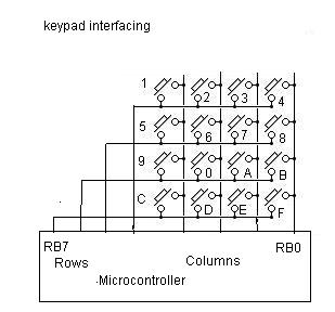
Can anyone help me? I need to get a code for this 4x4 Keypad with the PIC18F4520, and i have been looking around the net for hours and hours, but i have not come across what i need. I could have miss some out as i simply don't udnerstand a thing...

I need to hand in this research in like 2 or 3 days time. Could anyone help? I have totally no idea how to go about now, considering how tired and sleepy i have been these days...

Thanks in advance.
 

4x4 keypad how to make

The lecturers never exactly taught us how to do C programing, especially since this Keypad is something we have never touched before during class. The point now is that i need research materials, such as sample codes that i can possibly cite.

I will really appreciate it if someone could help me.
 

4 x 4 keypad

i can help you to have clear idea and i can guid to do code and hardware but i cant give you the source code............

then let me know.. will you?
 

p18f4520 keypad code

here is a method... but dont have the code .......
The advantage of this system is that it doesnt need any external power cktry and simple.... and also works perfectly
54_1243955638.jpg

First of all a lookup table has to be created. here port b is used. Out 0x0F to PORT B, then out 0xF0 to Port B. Then OR the result and store it in a buffer. ie if no keys r pressed then the value in buffer will be 0XFF.
Now for example, if key 4 of the above figure is pressed, 0X0E will be the value when 0x0F is outputted from PortB. (here B0 will become 0 as the switch is pressed (00001110)). On the other hand, 0XE0 will be the value when 0XF0 is outputted (B4 becomes 0 (11100000)). when ORed the value in buffer will be 0xEE (x=0XEE). Now assign 0XEE with value 4.
Like this way make look up table for the whole keys. Using switch statement, a particular number could be assigned to the value in buffer.

Try this and reply back..............
 

how to use keypad p18f4520

blueroomelectronics said:
Guess it would have helped if you paid attention in class.


lame
 

Re: p18f4520 keypad code

Hello,


I found ur method useful for my app. I have written code using ur method for scanning 3 x 3 matrix keypad. However, it is not generating all 9 codes for 9 keys.
Could u please find the bug in my code ?

// Make rows output and columns input
Configure_PortB_as_Output(); // Set Row as Output
Configure_PortC_as_Output(); // Set Column as Output
LATBbits.LATB2 = 0; // Write Row
LATBbits.LATB1 = 0; // Write Row
LATBbits.LATB0 = 0; // Write Row
LATCbits.LATC3 = 1; // Write Column
LATCbits.LATC2 = 1; // Write Column
LATCbits.LATC1 = 1; // Write Column
Configure_PortB_as_Input(); // Set Row as Input
u16Row = PORTB;
Configure_PortC_as_Input(); // Set Row as Input

// Make columns output and rows input
Configure_PortB_as_Output(); // Set Row as Output
Configure_PortC_as_Output(); // Set Column as Output
LATBbits.LATB2 = 1; // Write Row
LATBbits.LATB1 = 1; // Write Row
LATBbits.LATB0 = 1; // Write Row
LATCbits.LATC3 = 0; // Write Column
LATCbits.LATC2 = 0; // Write Column
LATCbits.LATC1 = 0; // Write Column
Configure_PortC_as_Input(); // Set Column as Input
u16Column = PORTC;
Configure_PortB_as_Input(); // Set Column as Input

u16ScanStatus = ((u16Row << 4) | u16Column);

Thank You,

Sunil Sawant


here is a method... but dont have the code .......
The advantage of this system is that it doesnt need any external power cktry and simple.... and also works perfectly
54_1243955638.jpg

First of all a lookup table has to be created. here port b is used. Out 0x0F to PORT B, then out 0xF0 to Port B. Then OR the result and store it in a buffer. ie if no keys r pressed then the value in buffer will be 0XFF.
Now for example, if key 4 of the above figure is pressed, 0X0E will be the value when 0x0F is outputted from PortB. (here B0 will become 0 as the switch is pressed (00001110)). On the other hand, 0XE0 will be the value when 0XF0 is outputted (B4 becomes 0 (11100000)). when ORed the value in buffer will be 0xEE (x=0XEE). Now assign 0XEE with value 4.
Like this way make look up table for the whole keys. Using switch statement, a particular number could be assigned to the value in buffer.

Try this and reply back..............
 

Status
Not open for further replies.

Similar threads

Part and Inventory Search

Welcome to EDABoard.com

Sponsor

Back
Top