Vermes
Advanced Member level 4


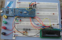
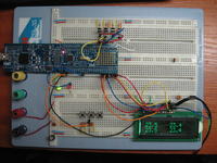
The code was made on LPCXpresso plate. This version is compatible with LPC1343, but it uses only GPIO and 16- or 32-bit timer. That is why after some minor modifications, the code could possibly work with a cheaper version LPC1114 or another Cortex. The entire software was written in IDE LPCXpresso. The project should be easily imported to another self configured toolchains using Eclipse.
The codes contain implementation of:
- ms and us delay function
- 1 Wire support
- ds18b20 sensor support with checking CRC
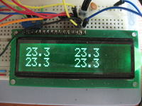
- HD44780 display support
- GPIO support (implemented by NXP)
1 Wire bus was handled using the GPIO built in uC. It can be used successfully to support other systems operating 1 Wire. Here are the three basic functions: readbyte, writebyte and reset. Physical derivation of 1 Wire is not predetermined (e.g. by #define). This allows you to connect multiple receivers to physically different pins and work with the library. Derivation is specified by a structure that contains two numbers – one is the port (0-3) and the second contains the pin number (0-11).
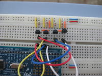
Functions to support the DS18B20 sensor use these functions (1 Wire). In the implementation there is the CRC control of the data received from the sensor. So you always know that the data received is correct. Functions also accept the structure describes above as an argument. Without any problem you can connect a few sensors to the processor, so you do not have to know the serial numbers of the sensors and perform the sensors search operation on the bus. The sensors should be connected in a standard way, what means the data line with pull-up (up to 3,3V with a value 4k7ohm) connected to the uC output.
Functions of the display on the HD44780 driver are the same as everywhere. You should use a display compatible with the driver, power it with 5V and connect to 5V pins tolerant on the uC. RW should be connected to GND (do not read data nor the flag, just save the data). Potentiometer like in a standard application. The backlight is connected permanently.


Link to original thread (useful attachment) – Termometr 4 punktowy na LPC1343 + 4x ds18b20 + src
Last edited:
