Continue to Site

Welcome to EDAboard.com

Welcome to our site! EDAboard.com is an international Electronics Discussion Forum focused on EDA software, circuits, schematics, books, theory, papers, asic, pld, 8051, DSP, Network, RF, Analog Design, PCB, Service Manuals... and a whole lot more! To participate you need to register. Registration is free. Click here to register now.

3 phase delta supply 100W

cupoftea

Advanced Member level 5
Joined
Jun 13, 2021
Messages
2,611
Helped
54
Reputation
108
Reaction score
115
Trophy points
63
Activity points
13,686
Hi,
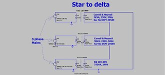
The attached doesnt work to give a 100W -ish 3 phase delta supply.
The 5A fuse just blows very quick.
Is it mainly because of the leakage inductances?

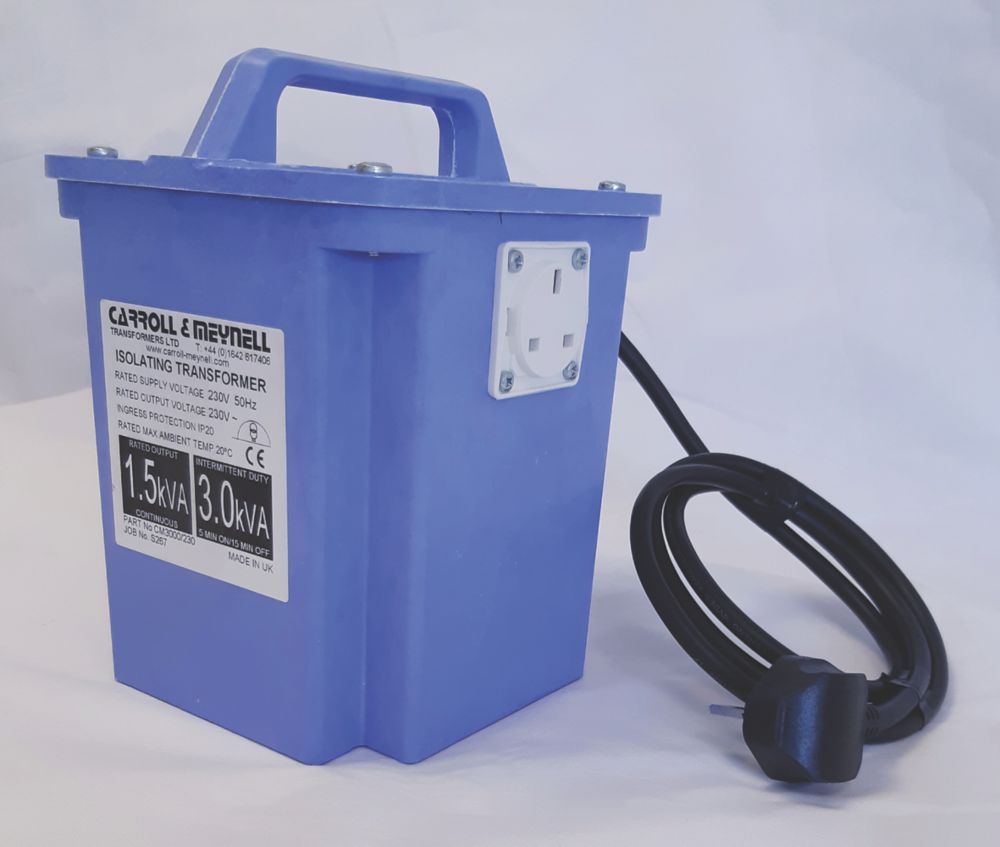
Transformers used were Carroll & Meynell 3000VA.


DELTA__.jpg
 

Attachments

  • delta_.zip
    1.3 KB · Views: 37
Last edited:
Surely not leakage inductance. More likely magnetizing inductance and its saturation during power-on. You want a soft-start, either by voltage ramp or current limiting resistors.

Additional problem is that three sources in delta connection are over-determined. A small voltage or phase deviation from ideal 3x120° causes large error currents.

Better use star connection or omit one source in delta.

You don't tell what the voltage source are and where you have fuses.
 
Thanks, the setup is
3phase mains. -> 3 phase variac -> three 5A fuses, one to each isolation transformer input . -> Secondaries connected in Delta --> 3 phase outputs to PCB connector --> 6 diode bridge --> NTC --> 220uF el cap.....etc etc

...its the 5A fuse that blows at switch on....doesnt matter...even happens when i slowly ramp the 3ph variac up from 0V.....the variac hums like heck for a few seconds, then the 5 Amp fuse blows......then the two remaining-in-circuit isolation transformers do supply the load...but with 3 sines, and one of them is twice the magnitude that it should be....and the three sines seen are not in the usual 0degs, 120degs, 240degs phase grouping....one of them is out of order.
 
Sounds like wrong transformer wiring or unequal winding ratio.
Whatsoever, as stated it's a bad idea to connect three voltage sources in delta, so just don't.
--- Updated ---

With two active sources, you should be able to see where the fault is by measuring individual circuit voltages and sketching a phasor diagram.
 
Last edited:
Due to Remanence from residual magnetic field stored, you may exceed the core magnetization current if the initial phase of voltage does not match the phase when shut off. If it is the exact opposite phase , it may saturate the core until demagnetized into the linear zone.


But it looks like it is wired incorrectly.

Ensure each output has the correct amplitude & phase using Y-Y connection before wiring to Delta.
--- Updated ---

sim is ok https://tinyurl.com/yn39o6lb because no Remanence
 
Last edited:
2 are C&M as above...one is small yellow one.....we didnt have 3 C&M's.
FvM You kindly say dont connect voltage sources in series...but thats what delta is all about?
 
Provided the transformers are all 1:1 as suggested by the simulation schematic, most likely fault is flipped connection of one transformer. You get 193 instead of 100 V for the summed voltage.
 
Last edited:
Thanks, i will get an LCR and make out the phase dots for each txformer, then reconnect them if neccesary
--- Updated ---

Additional problem is that three sources in delta connection are over-determined. A small voltage or phase deviation from ideal 3x120° causes large error currents.
Thanks, i see your point...on the sim, one source a few degs out causes overly high currents.
Delta does seem pretty horrible...only advantage the use of only 3 wires.
 
Last edited:
Even if the supply uses star connection, 3 wires are enough. The neutral can be left unconnected if the load is delta or symmetrical star.
This is why all grids only use Delta for transmission and Y for distribution to loads. I believe Neutral to Earth may improve load regulation from unbalanced loads and sources.
 
Thanks
Our 3 phase delta supply, which was made as in the following attached, does not work....we just "ringed" three isolation transformers, (and they were the right way round) each connected to a phase of a 3 phase star supply.
I believe that the fact that only two of the isolations transformers were matched was the problem...this thing just blows a fuse as soon as is powered up...even when we bring up slowly with three phase variac giving the star.
I believe one of the isolation transformers just saturates.
Would you agree?

I am wondering if it will work if we use three of the Carroll & Meynell ones? (we only have the two, so would need to buy another)
(LTspice and jpeg as attached)
 

Attachments

  • Star to delta _doesnt work.jpg
    Star to delta _doesnt work.jpg
    99 KB · Views: 56
  • Star to delta _doesnt work.zip
    1.1 KB · Views: 56
Hi,

as FvM already mentioned this delta connection is over determined.
At least there are Rser to compensate for calculation errors.

And the fact that all transformers have different inductivity and Rser does not help to get a meaningful simulation.
All should be as symmetric as possible.

I´d chose the more error tolerant solution and connect the output of the transformers as star, but the load as delta.for sure it needs the voltage to be adjusted.

Klaus
 
To understand if you see only a slight winding ratio mismatch or a fundamental polarity error, open the delta ring and measure voltage difference.

Thanks, it definitely wasnt polarity error , i had , at pne point, 82R in series with the outut of each secondary...and then connected tham in delta, and then raised the voltage up on the primary side with the 3 phase variac.....and did this with only some 10-15VAC so it wouldnt give much current...and then switched the connections of each secondary in turn, and then back again...but nothing worked......with them on open cct i had the typical 3 phase voltage appearance.....soon as you delta tham...one always goes much smaller and the phases dont even look 3 phase 120 degrees.
--- Updated ---

Inductance mismatch will cause imbalanced startup currents on the transformer with the smallest L.
Thanks, i was using three phase variac and rising voltage very slowly up from zero.
 
Last edited:
Thanks, it definitely wasnt polarity error , i had , at pne point, 82R in series with the outut of each secondary...and then connected tham in delta, and then raised the voltage up on the primary side with the 3 phase variac.....and did this with only some 10-15VAC so it wouldnt give much current...and then switched the connections of each secondary in turn, and then back again...but nothing worked......with them on open cct i had the typical 3 phase voltage appearance.....soon as you delta tham...one always goes much smaller and the phases dont even look 3 phase 120 degrees.
--- Updated ---


Thanks, i was using three phase variac and rising voltage very slowly up from zero.
Why does #1 schematic not show it ? I was referring to the mismatched transformers, not the variac.
 

LaTeX Commands Quick-Menu:

Similar threads

Part and Inventory Search

Welcome to EDABoard.com

Sponsor

Back
Top