SK245230
Member level 3
Hi,
I am trying to draw the equivalent model of more than 2 coupled inductors.
For two coupled inductors, the equivalent model is the one below.

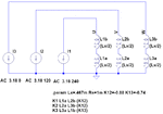
For two inductors coupled to a third one, I have found this:

This circuit was found with the formulas from here and by neglecting M23:
**broken link removed**
If some of you could help me to find a better circuit than this and that includes M23. Maybe someone knows the rule of how to draw these coupled inductors equivalent models of more than 2 inductors.
I am trying to draw the equivalent model of more than 2 coupled inductors.
For two coupled inductors, the equivalent model is the one below.
For two inductors coupled to a third one, I have found this:

This circuit was found with the formulas from here and by neglecting M23:
**broken link removed**
If some of you could help me to find a better circuit than this and that includes M23. Maybe someone knows the rule of how to draw these coupled inductors equivalent models of more than 2 inductors.
