Continue to Site

Welcome to EDAboard.com

Welcome to our site! EDAboard.com is an international Electronics Discussion Forum focused on EDA software, circuits, schematics, books, theory, papers, asic, pld, 8051, DSP, Network, RF, Analog Design, PCB, Service Manuals... and a whole lot more! To participate you need to register. Registration is free. Click here to register now.

2kW battery charger topology

Status
Not open for further replies.
I could run it at a higher frequency (100kHz) to minimize the inductor size.
The problem designing the inductor will be the peak current.
At 40 amps average the peak will be around 63 amps, plus switching ripple on top of that.
Absolute current peak may be something like 80 amps, which is not in itself a problem.

But then you need to think about skin effect in the inductor.
At 100 Khz the thickest wire you can use is about 0.4mm diameter which will carry about 360mA per strand.
At 20 Khz about 0.9mm wire can be used that will carry about 1.8 amps per strand.

The required inductance will be so low that only one or two turns may be required.
Core saturation is obviously important, and also core loss for heating reasons.

After thinking about all this for a while, If I was doing something like this myself, I would probably use a short length of copper tube with several powdered iron toroids slipped over it, and run it at a much lower switching frequency.

I have not done any calculations on this, but from past experience I might start with 10mm OD copper tube with perhaps 0.7mm wall thickness.
That should easily carry the high frequency current with negligible heating.
Then slip one powdered iron toroid over it and calculate what the core saturation and losses were at 80 amps, for one toroidal core by itself, and how much inductance I ended up getting.

With a bit of messing about, it should be possible to slip several (?) suitable toroids over the tube to meet all of my requirements.

With this type of very low inductance very high current, its physically much easier to wrap the core around the wire, than wrap the wire around a core.
Also keep an open mind about switching frequency.
Your copper pipe may make several tens of Khz possible.
But permiability and core loss of readily available (cheaper) cores may force a much lower switching frequency, which is not really a problem.

What I am saying is, select the switching frequency to suit the magnetics you can build, rather than starting off selecting some impractically high switching frequency and then getting into real grief trying to make it work.
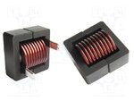
 
Thank you very much for the comprehensive answer, @Warpspeed.

You're right, I put the cart before the horse. But that's because I already have some commercial high current inductors (180Am, 13uH) like this:

180A-13uH.jpg

As you can see, the only problem is their low inductance hence I was thinking of pushing up the sampling frequency to workout this issue.

I didn't have time to make some calculations yet but I doubt I could use it (well, I have two of them) if the frequency will be lower.

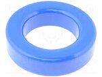
I also have this Arnold big toroid (sendust) cores (inner diam: 35mm, outer diam: 58mm, height: 15mm):

id34-od58.jpg

They have a large inner diameter (34mm) thus I could insert not one but four 16mm copper tubes but I don't know how to loop them (though I have a copper pipes welding equipment!).

I was thinking of some sort of litz wire (before you have suggested the copper pipes) as I have some bulk 0.7mm transformer wire available.

Either way, it will take some time to build such an inductor hence my first option to use the commercial one.

What's your oppinion about that?
 

I ran some numbers with powdered iron toroids, and a single pipe through the middle just falls way too short on inductance to be workable.
As inductance rises with turns squared, and inductance only increases directly with the number of cores in series, the only practical solution to get enough inductance involves more turns.

Litz wire is definitely possible, but its an awful job stripping and tinning all those individual wires, but its certainly possible and would work.

Foil is good too, but to carry 80 amps it would need to be thick which makes it infexible. I did once make a 1.5 Kw boost converter out of 1/4 inch copper fuel line tube, eight turns on a very large UI core, and that might work for you too.
It worked well, but the core was much larger than it really needed to be, but that was o/k because I already had several.

The really unusual thing about this was that the secondary ran right through the middle of the primary (like coax) and this gave absolutely minimal leakage inductance.
It was another of my hair brained ideas that worked out much better than I dared to hope for. The tube is like 30mm wide 0.7mm foil wrapped in a circle and would carry 80 amps average very easily.

inductor.JPG

I know something similar (without the secondary) would work for you too, but the core is rather on the big side.
 

That's a really bright idea (coax type windings).

I did once make a 1.5 Kw boost converter out of 1/4 inch copper fuel line tube, eight turns on a very large UI core, and that might work for you too.

Unfortunately, it's much harder to wind a copper tube on a toroid core (though the idea is brilliant, too). I guess I'm left with the only practical solution: the litz wire. I'll try sourcing for a commercial made one and, in the mean time, I'll build the rest of the circuit. Thank you once again for your time.
 

Yes, both copper tube and foil are both very impractical for a toroid, but Litz is a definite goer.
All things considered it probably the best choice.

With a toroid there are three things, inductance, saturation level, and core loss.
And only one thing you can change, the number of turns.
To get all three right requires a very careful selection of core size and material.

For a home brew effort, gapped ferrite may be a better choice. Not because its any better, but the ability to tweak the air gap means that its going to work first go.
 

Thanks for the protection tips, too. Anyway, I already have a dedicated circuit to monitor the batteries state. I set it up to disconnect the transformer from the mains if an overcharge occurs (then, after few minutes, it turns off the generator, too).
..thats good, and hopefully you will have a protection at the actual output of the boost converter to shut it down in case you accidentally turn it on when the load is not connected.

- - - Updated - - -

I am sure you are aware that current sources on no load need overvoltage shutdown protection….not on the battery, actually on the converter.

- - - Updated - - -

..well, on the battery , of course "aswell"
 

For what you want, the sense resistor would be your best bet, dont over do it.

I have 1.5KW converters with a 0.1 Ohm resistor (5W) and it never gets too hot to touch.

I dont quite get your topology. So you boost with the PFC to feed on a LF magnetic transformer? Or are you trying to boost from the transformer output into your batteries?

Why not use a buck PFC converter straight from the generator? The output is low enough to have PF > .9 and the efficiency will be much higher than passing it trough a transformer. The converter itself can be current limited, ready to feed into the batteries
 

not sure OP is still around so ill answer from our discussion...OP wants isolation, so used the LF transformer, Because he had one lying around.But he also wants good power factor, or a reasonable power factor, so he is talking about the converter that is simulated in post#18 here.
 

Status
Not open for further replies.

Similar threads

Part and Inventory Search

Welcome to EDABoard.com

Sponsor

Back
Top