Continue to Site

Welcome to EDAboard.com

Welcome to our site! EDAboard.com is an international Electronics Discussion Forum focused on EDA software, circuits, schematics, books, theory, papers, asic, pld, 8051, DSP, Network, RF, Analog Design, PCB, Service Manuals... and a whole lot more! To participate you need to register. Registration is free. Click here to register now.

28BYJ-48 stepper motor

Status
Not open for further replies.

voso

Newbie
Joined
Feb 3, 2021
Messages
3
Helped
0
Reputation
0
Reaction score
0
Trophy points
1
Activity points
26
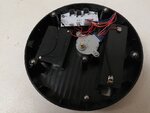
I have a 135mm diameter turntable for models. powered by the 28BYJ-48 stepper motor using a 5v transformer. I have set the unit to rotate clockwise at 2rpm with full 360 degree rotation.
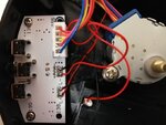
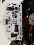
However after turning it off and then back on It does not restart. If I press a button it then restarts at clockwise 2rpm full 360 rotation. Is it possible to make the unit restart when the power is turned back on? It is a Chinese unit and has three buttons with a circuit board which I do not understand! I am hoping it is just a matter of soldering in a jumper wire to make it restart when powered on. Due to the unit being in a display cabinet it is not feasible to press a button every time. I hope someone can help me!!!
 

I am hoping it is just a matter of soldering in a jumper wire to make it restart when powered on.

I too think so unless there is a microcontroller running the show. At low RPM the motor may be used as a direct drive instead of gears and belts.

But we cannot say anything confidently unless we can have a look at the anatomy! If you can open it up and take a few good photos and post them.
 

c_mitra.
Thanks very much for your help. have attached three pics which I hope will make sense to you.
I am much more of a mechanical guy than a electronics guy!
 

Attachments

  • 1.jpg
    1.jpg
    103.3 KB · Views: 131
  • 2.jpg
    2.jpg
    115.2 KB · Views: 75
  • 3.jpg
    3.jpg
    95.7 KB · Views: 77

I could not make out much!

The motor appears to have internal gears (because the drive spindle is offset from the axis). The speed reduction increases the torque and a small motor can be sufficient. I cannot make out the labels on the ICs but they are related to drive circuit.

The stepper appears to be a simple unipolar 5 wire device (see https://www.instructables.com/4-5-6-and-8-wire-Stepper-Motors/) and the two ICs are the drivers (see pic 3.jpg near the bottom, two ICs at right angles).

One of them is a driver and the other may be the real controller. I could not make out much.

In the worst case, you can solder two wires from the switch and bring them out to any convenient position. As these are low frequency devices, you are unlikely to have any problem.
 

One of the ICs on the pcb is ULN2003. The other one is, probably, microcontroller.
As for the motor, it is unipolar motor, 5 wires, common wire connected to positive supply, phase wires connected through ULN to ground sequenced by microcontroller.
 

c_mitra and ZASto, thanks very much for your info.
c_mitra--I have soldered two wires to the switch and it works fine. I will purchase a switch and fit it to the outside of the cabinet.
A brilliant solution, it is great to know that there are experts who are willing to pass on their knowledge free of any charge to an unknown person.
 

c_mitra--I have soldered two wires to the switch and it works fine. I will purchase a switch and fit it to the outside of the cabinet.

Glad to know that it worked out fine.
 

Status
Not open for further replies.

Similar threads

Part and Inventory Search

Welcome to EDABoard.com

Sponsor

Back
Top