Continue to Site

Welcome to EDAboard.com

Welcome to our site! EDAboard.com is an international Electronics Discussion Forum focused on EDA software, circuits, schematics, books, theory, papers, asic, pld, 8051, DSP, Network, RF, Analog Design, PCB, Service Manuals... and a whole lot more! To participate you need to register. Registration is free. Click here to register now.

220V voltage to digital voltage

Status
Not open for further replies.

EthanAlef

Newbie level 5
Joined
Apr 29, 2013
Messages
9
Helped
0
Reputation
0
Reaction score
0
Trophy points
1,281
Activity points
1,346
I use two LDOs to obtain digital voltages. Finally I get 3.3V at the end.
However, when I connected something, such wifi module, which must be driven by 3.3V, the voltage at that terminal drops down to 1.9V.

I am beginner in electronics design. My only knowledge tells me I should add an extra capacitor at the terminal, but I don't know what value should it be...

Or, if there any solution to such problem? Please see the attached.

Screen Shot 2013-04-29 at 5.57.02 PM.png
 

The datasheet clearly mentions,

The LDO output is stable when using only
1 µF output capacitance. Ceramic, tantalum or
aluminum electrolytic capacitors can all be used for
input and output.

Generally, this voltage drop happens,

1. If your regulator is unable to provide sufficient cuurent or
2. If your regulator is in unstable state(That might be the case with your design) or
3. Sometime to your bad luck the batch of regulators you buy might be giving you problems (This is some dirty case and you may experience sometime or later)

Your case, use capacitor as mentioned in datasheet, intially you can have a try by removing the cap at Wi-Fi side..
 
I think I should increase the output current as much as possible in order to supply 3.3V at the output of the 3V3 LDO with the wifi module connected. Can you suggest a way to increase the voltage at the output of the 3V3 LDO?
 

Whoa. There's a lot more wrong here than just the issue of an undervalued output capacitor on a voltage regulator!

First and foremost - this is a transformerless power supply - with all of the attendant safety implications that these sorts of circuits bring. They're not necessarily bad - indeed, they're the right solution to some problems, but they demand healthy respect and understanding. They're often discussed on this forum and well covered by this microchip application note: ww1.microchip.com/downloads/en/appnotes/00954a.pdf.

The things that makes the big red flag pop up in my mind is the presence of J1 - the external 9V connector. Generally, one should avoid any source of human contact with any of the components comprising, or attached to these types of power supply. The assumption that "GND" is ground (or the neutral conductor is indeed at GND potential) is an assumption... and I've seen it wrong often enough that I wouldn't want to stake my life on it. The electrical test guys I work with tell me that they find reversed active/neutral conductors in ~5% of the IEC power leads they test!

Having said all that - proceed as you wish, just be careful :)

To answer your question though, no - your problem is highly unlikely to be due to inadequate output capacitance (they're only there for stability/transient response). It's more likely you're asking for more current that you can draw through the 0.47u mains capacitor... but have a read of the app note and decide for yourself!

That J1 port is for troubleshooting. Once the 220V is supplied, the J1 should not be connected.
One of the solution is to replace the regulator. But I am thinking if there any way, such as increasing/decreasing capacitance, to obtain more current output?
 

thylacine1975 is absolutely correct about the mains safety!

If you take power off between the live mains and the safety Earth conductor, it needs to be a current smaller than commonly is allowed for input filters in computer-type switchmode power supplies.

What you have in the diagram qualifies as a mains "leak". If you try to take off too many mA, you get to the point where the RCCD (Residual Current Circuit Breaker) will trip out and cut the power to that circuit in the building. Normally set at about 30mA to reduce nuisance tripping. Know also that you can die from 12mA through your body, and the circuit breaker will not trip! The neutral should be connected to the ground at the input to the building, ie. on the other side of the breaker.

Much better to use 2 capactors, one to live and one to neutral. They must not be electrolytic. 220V AC is 311V peak, so they should be rated to 400V minimum.

You should include a upstream fuse in the live. Using 2 capacitors means you need to double the value for the same current (because they are effectively in series).

The current you can get from this circuit.. ?
Firstly , you need to know if the cause of the drop-out is the collapse of voltage at the junction of the 0.47uF mains capacitor and R11 .. or if it is because of a collapse of voltage across the zener diode after R11. If it is at the capacitor, then you need to increase the capacitor value, say by putting another in parallel. If it is at the zener, you need to lower the value of R11.

Essentially, if you are not taking current from the circuit, then it is all going into the zener diode, heating it up a bit. As you do take current, less gets dissipated in the zener. If you take it all, the voltage at the zener will collapse, starving the regulator. How much is available is decided by the difference between about 311V and the zener voltage. The current available is about (311-Vzener)*1000/R11 in mA. You set R11 to give you what you need.

CHECK that the ripple current rating for the capacitors is enough!

This type of circuit is only suitable for tiny miniscule power. If you need more, then use a small power adaptor. My place is full of them Every modem, phone charger, flashlight charger, etc. A 9V DC "wall wart" is easy to come by, cheap, safe, and way easier than messing with capacitor driven stuff directly connected to 220V AC. Come to think of it, that is a much lower cost way than knocking ourselves out trying to design a different one.

Thank you for you guys' comments.
Actually I am designing a Power Meter with RF sending data to other device.
My design is reference to Microchip's power meter reference design.
The link is: **broken link removed**

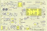
The schematic diagram above is one of the circuits.
For my whole design, please kindly see the attached.
Schematic (no logo).jpg

So far I still have no idea why they use LIVE as ground instead of Neutral.
 

Attachments

  • Schematic (no logo).jpg
    Schematic (no logo).jpg
    732.4 KB · Views: 175
Last edited:

That it is a power metering device explains much.
OK - take carefull note. In the section "Low Power for Digital", you see that there are two grounds.
GNDA is the "low" of the AC input. GNDB is the 0V for all the circuits driven by the DC regulators.
There is no obvious path where they might couple sufficiently to make the capacitor connected power-stealing circuit complete to let any current into the zener D3.
If there is somewhere in there, I missed it.

I am cautious about thinking the whole reason the first part of the low power DC regulators starving is because of the circuit non-completion between GNDA and GNDB.

I do not fully understand how it is all intended to work, but given what it is supposed to do, it may be essential for the circuit samplers to be able to connect to the live, neutral, and earth separately. It may be necessary for the power metering circuits to be able to work relative to the ground common-mode voltages, which can be high and noisy.

You can try connecting GNDA and GNDB temporarily, and see if the low power DC circuit regulators suddenly start working OK - but take care! There must be a reason they were designed to be separate.

Yes. GNDA and GNDB are connected together by an inductor(ferrite bead), in order to eliminate high frequency noise and is requested by the energy-metering IC.
 

Status
Not open for further replies.

Similar threads

Part and Inventory Search

Welcome to EDABoard.com

Sponsor

Back
Top