Continue to Site

Welcome to EDAboard.com

Welcome to our site! EDAboard.com is an international Electronics Discussion Forum focused on EDA software, circuits, schematics, books, theory, papers, asic, pld, 8051, DSP, Network, RF, Analog Design, PCB, Service Manuals... and a whole lot more! To participate you need to register. Registration is free. Click here to register now.

[Questions] How to simulate this FM reciever

Status
Not open for further replies.

oasis4355

Member level 3
Joined
Feb 28, 2006
Messages
67
Helped
0
Reputation
0
Reaction score
0
Trophy points
1,286
Activity points
1,801
ujt 2n2646 spice model

Hi all,

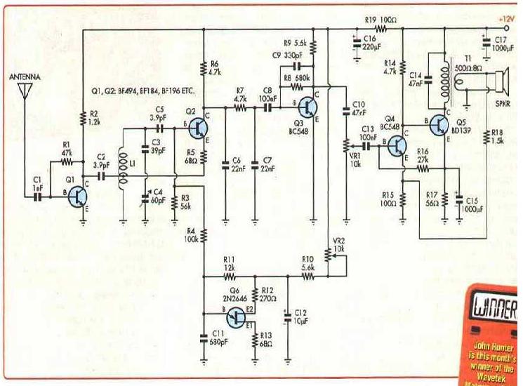
i found this circuit online.

**broken link removed**


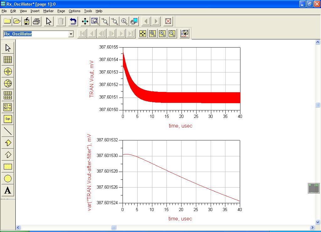
I understand that Q6 is a quenching, but what does it do? How can i simulate the whole thing? It's hard for me to simulate it while i don't have any understanding on quenching circuit. I was hoping someone can advice me on this.

Thanks in advance

Alex

90_1172953857.JPG
[/img]
 

2n2646 spice model

Q6 is just a simple 50kHz osc who's output gets mixed in with the received RF signal in Q2 to obtain the IF, which will contain both AM and FM components. Q2 have 2 functions, mixing and detector.
 

ujt spice model

Thanks for the info E-design. So, it act's like an LO? but why it must be 50kHz? can it be other value?

Thanks
 

modelo 2n2646 para orcad

Q6 in not a LO. This is a super regenerative receiver. Quenching is needed to periodically set oscillation of Q2 ON and OFF. In this way the average gain of Q2 is very high, thus the sensitivity of receiver.
Vhen simulating such circuit first try to find propper bias for Q2 at which it will oscillate. This bias should be in the voltage range of C11 sawtooth voltage.
Everything is on your url.
 

Hi borber,

I'm still new in electronics (first year), why does turning on/off of the oscillator improves the sensitivity and the gain of the reciever?

Thanks in advance
 

At suitable bias, just before oscillation starts and because of positive feedback the circuit has increased gain. This point is not stable and quenching is just sweeping bias arround this oscillation point with 50kHz frequency.
 

Hi borber,

thanks for your information, i really have a better understanding.

However, when i try to simulate with ADS, i couldn't find the unijunction transistor 2N2646, and there aren't any equivalents to insert into the schematics.

How should i proceed? can i download the libraries from the net?
 

I do not know if ADS can use PSpice model. Here it is:

* SUBCKT 2N2646 1 2 3
*Connections Emitter Base1 Base2
.SUBCKT 2N2646 1 2 3
DE 1 4 EMITTER
VE 4 5 DC 0
HVE 6 0 VE 1K
RVE 0 6 1MEG
BBB 5 7 I=0.00028*V(5,7)+0.00575*V(5,7)*V(6)
CBB 5 7 35P
RB1 7 2 38.15 RMOD
RB2 3 5 2.518K RMOD
.MODEL RMOD R TC1=.01
.MODEL EMITTER D (IS=21.3P N=1.8)
.ENDS 2N2646
 

Hi borber,

I try using the model in ADS, it didn't work.

I've just downloaded and install Orcad Pspice 9.2, how should i proceed with the codes you gave me?

Thanks
 

siimply use netlist translator in ads , so it translate the model of pspice to ADS compatible model

Khouly
 

I do not use Orcad and can not give precise instructions.
Generally, you should place this model txt into a suitable (txt format) spice library (uce copy/paste) and use or create UJT shape. Then you create componnent 2N2646, associate it with subcircuit and shape.
 

Hi borber,

I read the link below, and found out more about UJT. Assuming the peak voltage of the sawtooth waveform is around 7V, i used a sawtooth waveform generator at 50kHz to quench the oscillator. and the RF input i set for 300mV at 100MHz.

https://baec.tripod.com/DEC90/uni_tran.htm


[Referring to figure 1, 2] However, i'm not sure what i'm looking for in this simulation. Something seems wrong. I wonder if someone can advice me on this issue.

[Referring to Figure 3] And i've try to make the oscillator to oscillate without the RF input and the quenching, the output is the dc voltage (18V supply), and i don't think this is also right. Please advice.


Thanks in advance


29_1173453323.jpg


6_1173453428.jpg


62_1173453515.jpg
 

You should look at collector of Q3 as output. RC filter after Q2 collector is essential. You wrong connected bias resistors for Q2, check schematics. Input RF voltage should be about 200µV and not 300mV.
To check oscillation point replace sawtooth generator with battery (DC voltage) and vary it's voltage (not over 7V) untill oscillator starts oscillating. If it dont oscillate lower 100k resistor.
 

Thanks Borber,

the comments you gave works well. The oscillator starts oscillating. However, the amplitude of the sine wave (output from the oscillator) is less than 1mV. Is this correct?

I have try the S-measurement on the RC filter, it seems it's a filter with cutoff frequency at 30kHz. Why is it essential?

Thank you for your time

79_1173472115.jpg


84_1173472199.jpg
 

1mV of RF signal is correct. You must use AM generator for input signal and modulating signal should appear on the output of RC filter.
Filters role is to block quenching signal entering the audio amplifier.
 

Hi borber,

Can i use FM signal in the input? Since it's a receiver for FM.

Thanks
 

You can but the signal frequency must be set to the slope of resonance curve.
 

Hi,

Thanks for the info Borber. Just to have a overall picture of this receiver, so the FM signal goes in the input of the oscillator, goes in the LC tank circuit. If LC is tune to 100 MHz, and the FM carrier is 100Mhz, at the collector of the oscillator transistor will be the modulating signal from FM, due to additive effect in the LC tank.

And at this point, the FM signal (100MHz) will be mixing the sawtooth quenching signal around 50kHz. Thus, we have a AM, and FM signal component at the base of the transistor. where FM signal component will be our modulating signal at the collector, and the AM component will be turning on/off the oscillation.

But i still have some questions about it.

[1] Varying the VR2 of the quenching circuit will actually vary the quench voltage or frequency. I understand that changing the frenquency will effect the sensitivity. But how does it affect it? and what will happen if the quench voltage, Vp increases? (I think i has something to do with sensitivity also, just want some comfirmation)

[2]Superregenartive reciever, the term "regenerative" is actually referring to the quenching signal which turns on/off the oscillation?

[3]As borber have mention to have a AM modulated signal for input and we'll have the modulating signal. How come an FM reciever and recieve AM signal?

Thank you for you time, please correct me if i'm wrong.
 

Status
Not open for further replies.

Part and Inventory Search

Welcome to EDABoard.com

Sponsor

Back
Top