Pastel
Member level 3
Hello guys!
I'm an absolute newbie in the FPGA world. I have some knowledge in programming microcontrollers, but
sometimes µC don't meet the timing specs, so I have to go one step further. First, here is what I'm using:
- De0 Nano board (from Terasic, with Cyclone IV).
- Quartus lite, the latest version that supports Cyclone IV, version 18.1
- Windows 10
- Oscilloscope plugged at the output.
I wanted to make a simple counter, that puts the signals to the output pins. Here is what I wrote.
NB: I will not go into the details of routing the q vector to the output, it does (more or less) what I
expect and there are signals on the 8 lsbs.
The code is pretty simple, but it raises many questions.
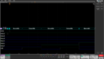
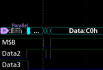
1. The functionality is almost what I intended to do, but there is a glitch on MSB and data2. Could anybody explain
why it happens? I can understand why the data don't switch all at the same time because I use wires that may have
some noise, and since this happens under one ns, then there is a place where the signals are not fully defined
(under the label "parallel"). But what happens to MSP and Data2? Why these small glitches?
2. I was assuming the counter would roll by itself and return to 0 after 2^16 cycles. But then since it doesn't work
I also tried to test if q == 65535 begin q <= 0; end but it doesn't change anything.
3. I wrote q <= q+1. Sometimes, I find some online examples like q <= 16'b1. What would it change? Is it
necessary to do this. Apparently in this example, it doesn't change anything, but I suppose there are good reasons
to write like this.
4. Is it necessary to use the quartus simulator if I have an oscilloscope on the output? What is the advantage of
this simulation?
Thanks for any hint!
Pastel
I'm an absolute newbie in the FPGA world. I have some knowledge in programming microcontrollers, but
sometimes µC don't meet the timing specs, so I have to go one step further. First, here is what I'm using:
- De0 Nano board (from Terasic, with Cyclone IV).
- Quartus lite, the latest version that supports Cyclone IV, version 18.1
- Windows 10
- Oscilloscope plugged at the output.
I wanted to make a simple counter, that puts the signals to the output pins. Here is what I wrote.
NB: I will not go into the details of routing the q vector to the output, it does (more or less) what I
expect and there are signals on the 8 lsbs.
Code:
module Counter(q, clk);
	output reg [15:0]q;
	input clk;
	always@(posedge clk) begin
		q <= q+1;
	end
endmodule
The code is pretty simple, but it raises many questions.
1. The functionality is almost what I intended to do, but there is a glitch on MSB and data2. Could anybody explain
why it happens? I can understand why the data don't switch all at the same time because I use wires that may have
some noise, and since this happens under one ns, then there is a place where the signals are not fully defined
(under the label "parallel"). But what happens to MSP and Data2? Why these small glitches?
2. I was assuming the counter would roll by itself and return to 0 after 2^16 cycles. But then since it doesn't work
I also tried to test if q == 65535 begin q <= 0; end but it doesn't change anything.
3. I wrote q <= q+1. Sometimes, I find some online examples like q <= 16'b1. What would it change? Is it
necessary to do this. Apparently in this example, it doesn't change anything, but I suppose there are good reasons
to write like this.
4. Is it necessary to use the quartus simulator if I have an oscilloscope on the output? What is the advantage of
this simulation?
Thanks for any hint!
Pastel