Continue to Site

Welcome to EDAboard.com

Welcome to our site! EDAboard.com is an international Electronics Discussion Forum focused on EDA software, circuits, schematics, books, theory, papers, asic, pld, 8051, DSP, Network, RF, Analog Design, PCB, Service Manuals... and a whole lot more! To participate you need to register. Registration is free. Click here to register now.

Helping solve the transfer function of RC circuit

Status
Not open for further replies.

neo93

Newbie level 2
Joined
May 7, 2017
Messages
2
Helped
0
Reputation
0
Reaction score
0
Trophy points
1
Activity points
17
Hi everyone,
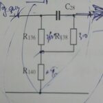
I'm stuck this circuit I attached. R136 = R138 = 300 KΩ; R140 = 15 KΩ (R140 connects to GND); C28 = 5100 nF; input is DC signal and output is on the other side of C28. Anyone can help the transfer function this circuit, please. Thank you very much.
 

Attachments

  • dsc_0202_2.jpg
    dsc_0202_2.jpg
    8.2 KB · Views: 59

This is 'sort of similar' to a bass-cut portion of a Baxandall tone control. It is not quite identical to the conventional circuit.

input is DC signal

By the way, you only get output if the input is an AC signal.
 

By the way, you only get output if the input is an AC signal.
There is a DC path through R136 and R138 but to derive any meaningful voltages you would have to know the source and load impedances.

Brian.
 

By the way, you only get output if the input is an AC signal.

R136 and R140 form a DC voltage divider. Hence, this voltage is available at the output (not considering any load).
 

To be honest, input signal is generated from phase splitter circuit ( make AC 400 Hz signal to DC signal). I wonder how this circuit affects to DC input signal. As @Bradtherad said, the C28 is useless in this case? or I mean, only the path through R136, R140 divider? The author said that this circuit will have special effect to input. But how? I'm stuck :)
 

Status
Not open for further replies.

Part and Inventory Search

Welcome to EDABoard.com

Sponsor

Back
Top